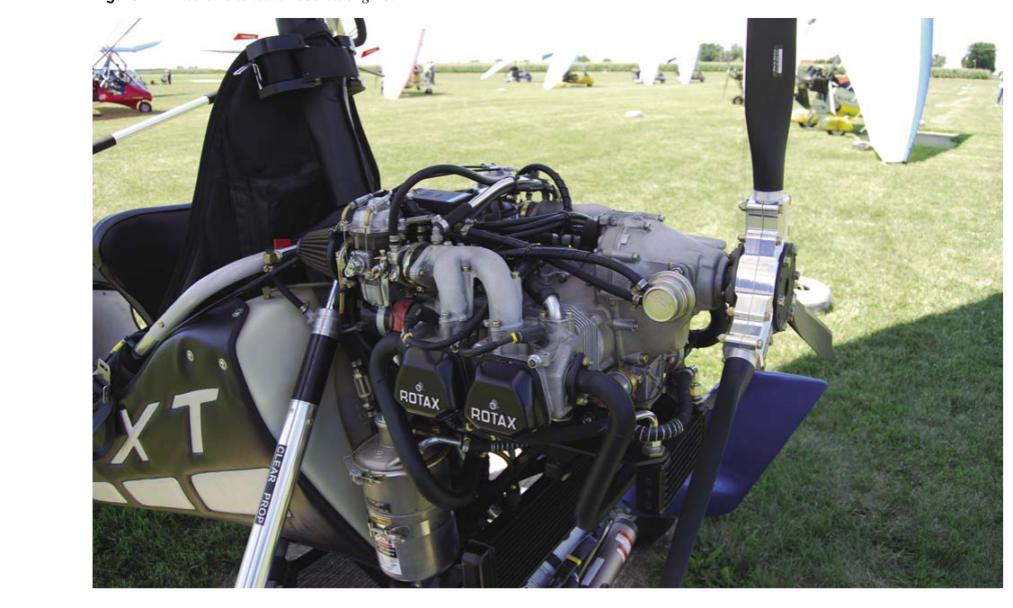
Most certificated light aircraft use air-cooled reciprocating engines, and while the cylinder fins visible on the outside do a significant share of heat removal, the engine oil system carries an equally important thermal burden. Oil absorbs heat from pistons, bearings, cam followers, and other friction surfaces that cooling airflow can never directly reach. That heat must then be extracted from the oil before the oil returns to the engine — a task handled by the oil cooling system. For AMT Powerplant students, mastering the design, components, and troubleshooting logic of oil cooling systems is both a certification requirement and a genuine safety competency.
This article covers how oil cooling systems are constructed, how they regulate oil temperature, the key specifications technicians must know, and the failure modes that show up on the FAA Powerplant Knowledge Test.
Why Oil Temperature Matters
Engine oil serves three simultaneous functions: lubrication, cleaning, and cooling. The cooling role is especially critical in air-cooled designs because the piston crown — the surface most directly exposed to combustion heat — cannot be reached by external airflow. Oil sprayed or splashed onto the underside of the piston crown carries that heat away. If oil temperature rises too high, the oil's viscosity drops, its film strength degrades, and oxidation accelerates, leading to sludge, varnish deposits, and accelerated bearing wear. Conversely, if oil runs too cold, it remains thick, does not circulate freely, and can carry water and acids in suspension rather than burning them off. Maintaining oil temperature within the manufacturer's specified normal operating range is therefore essential to engine health and longevity — normal and maximum oil temperature limits vary by engine model and are not universal; always verify the specific aircraft's Pilot's Operating Handbook, engine Type Certificate Data Sheet, or maintenance manual for the applicable limits.
How the Oil Cooling System Works
The oil cooling system forms a loop within the broader engine lubrication circuit. Pressurized oil leaving the engine's pressure pump is directed — depending on its temperature — either through an oil cooler or around it via a bypass path, before being delivered to the engine's bearings and other components. The key components are the oil cooler core, the thermostatic bypass valve, associated plumbing, and the airflow path that extracts heat from the cooler itself.
The Oil Cooler Core
The oil cooler is essentially a heat exchanger, most commonly of the air-oil type. It consists of a series of thin-walled passages through which hot oil flows, surrounded by fins and air passages through which ram air or propeller slipstream flows. Heat transfers from the oil, through the cooler walls, and into the passing air. The core is typically constructed from aluminum alloy for its combination of high thermal conductivity, light weight, and corrosion resistance.
Most general aviation oil coolers are mounted at the rear of the engine or at a location within the engine compartment where they receive consistent airflow. Some designs use dedicated air scoops; others rely on airflow directed through baffles. The cooler is almost always plumbed so that oil enters at one end and exits at the other, maximizing the temperature gradient between the oil and the airstream — a principle called counterflow or crossflow design depending on the relative direction of oil and air travel through the core.
The Thermostatic Bypass Valve
A fixed oil cooler with no temperature regulation would overcool oil during cold-weather operations and potentially undercool it in hot climates at high power settings. The solution is a thermostatic bypass valve (sometimes called a thermostatic oil cooler valve or oil temperature regulator). This valve is typically located at the oil cooler inlet or outlet and uses a temperature-sensitive element — often a wax pellet or bimetallic device — to modulate oil flow.
When oil is cold (below the valve's set point), the bypass valve opens a passage that routes oil directly back to the engine, bypassing the cooler entirely. This allows the engine to warm up quickly and prevents the cooler core from being subjected to extreme pressure differentials that cold, thick oil could create. As oil temperature rises to the valve's opening threshold, the bypass progressively closes and more oil is directed through the cooler. At normal operating temperature, most or all of the oil flows through the cooler core before returning to the engine sump or dry-sump tank.
This thermostatic action is critical: a stuck-open bypass valve will cause chronically high oil temperatures because oil is never routed through the cooler, while a stuck-closed bypass valve can cause oil pressure spikes during cold starts and overcooling in flight. Both conditions are detectable and are common test topics.
The Winterization Plate
In very cold operating environments, even with a thermostatic valve, the oil cooler may extract so much heat that oil temperature cannot reach its normal range. Many aircraft use a winterization plate (also called a winterization kit or cover plate) that partially or fully blocks airflow across the oil cooler face. This reduces heat rejection and allows the oil to reach and maintain its normal operating temperature. The FAA and engine manufacturers publish specific guidance on when and how to install winterization plates; installing or removing them is a scheduled maintenance task documented in the aircraft's maintenance records.
Airflow and Baffling Considerations
The oil cooler is only as effective as the airflow passing through it. Engine baffles and seals that are cracked, missing, or improperly fitted can drastically reduce airflow over both the cylinders and the oil cooler. A technician performing a high-oil-temperature squawk must always inspect the entire baffle and seal system, not just the cooler itself. Ram air enters the engine compartment through the front inlet, is directed by baffles over cylinder fins and through or around the oil cooler, and exits through cowl flaps at the rear of the lower cowling. Cowl flaps give the pilot direct control over airflow volume through the engine compartment and thus directly influence oil temperature — closing cowl flaps reduces cooling airflow; opening them increases it.
Dry-Sump vs. Wet-Sump Systems
The oil cooling circuit integrates differently depending on whether the engine uses a wet-sump or dry-sump system. In a wet-sump system (common on horizontally opposed engines in light aircraft), oil is stored in a sump at the bottom of the crankcase. A single pressure pump draws oil from the sump, circulates it through the engine, and returns it by gravity and scavenge action. The oil cooler is typically plumbed between the pressure pump outlet and the engine's main oil gallery.
In a dry-sump system (used on many larger radial engines and some high-performance aircraft), oil is stored in a separate tank external to the engine. One or more scavenge pumps actively remove oil from the crankcase and return it to the tank, while a pressure pump supplies oil from the tank to the engine. The oil cooler is often plumbed between the scavenge pump outlet and the external tank, meaning scavenged hot oil passes through the cooler before entering the tank. Dry-sump systems are generally preferred for high-output and inverted-capable engines primarily because of their greater oil capacity, more reliable oil control during high-G and inverted maneuvers, and reduced windage losses, rather than for simplified temperature management alone.
Key Numbers and Rules
- Normal and maximum oil temperature limits: Vary by engine model; always verify against the specific engine's Type Certificate Data Sheet and manufacturer's operating limitations rather than assuming a universal figure.
- Cold-start bypass: The temperature at which a thermostatic bypass valve begins to open or close is specific to the valve's design and the engine installation; consult the applicable component and engine manufacturer specifications rather than assuming a standard figure.
- Winterization plates: Are an approved aircraft configuration change; installation or removal must be recorded in aircraft maintenance records per 14 CFR Part 43.
- Oil cooler pressure testing: Cooler cores are pressure-tested per the specific manufacturer's overhaul manual when suspected of internal leaks; there is no single standardized test pressure that applies across all coolers, so technicians must always consult the applicable overhaul manual.
- Leak inspection: Any external oil found near the cooler fittings, hose connections, or core seams must be investigated; even a small leak can lead to catastrophic oil loss in flight.
Common Failure Modes and Troubleshooting
Understanding failure modes is essential for both the Knowledge Test and real-world maintenance.
High oil temperature in flight can result from: a stuck-open thermostatic bypass valve; blocked or reduced airflow through the cooler (debris, damaged baffles, closed cowl flaps); low oil quantity reducing the system's thermal capacity; a partially blocked cooler core; or an internal engine problem generating excess heat (detonation, stuck piston rings, excessive bearing clearances).
Low oil temperature can result from: a stuck-closed thermostatic bypass valve (forcing all oil through the cooler regardless of temperature); an improperly installed winterization plate that over-restricts airflow even in warm conditions; or a cooler that is oversized for the installation.
Oil in the coolant or coolant in the oil does not apply to pure air-cooled engines, but internal cooler core failure — where oil passages crack — can allow oil to enter the airstream or, in some engine configurations that use combination coolers, to cross-contaminate other fluid systems.
Common Test Traps
- Bypass valve function confusion: Students often reverse the bypass valve's action. As a simplified rule of thumb: cold oil = bypass path open (oil skips the cooler); hot oil = bypass path closes (oil is progressively routed through the cooler). Keep in mind the valve redirects flow rather than literally opening or closing access to the engine.
- High temp cause assumed to be the cooler: The FAA test frequently presents high oil temperature as cooler failure, but the correct first step is to investigate all possible causes — baffling, oil quantity, and cowl flap position — before condemning the cooler.
- Winterization plate as a pilot action: Installing or removing a winterization plate is a maintenance action requiring a log entry, not a preflight action the pilot performs at will.
- Pressure test values: The test may ask about cooler core integrity checking; know that this involves a bench pressure test per the manufacturer's overhaul manual, not a simple visual inspection.
- Wet vs. dry sump cooler plumbing: The location of the oil cooler in the circuit differs between wet- and dry-sump systems; do not assume one design applies universally.
A thorough understanding of oil cooling system design, regulation, and failure modes equips the AMT Powerplant candidate not only to pass the Knowledge Test but to diagnose real engine problems safely and efficiently — skills that directly protect the flying public.