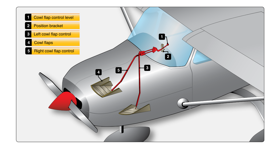
Reciprocating aircraft engines produce enormous amounts of heat as a byproduct of combustion — in fact, only about one-third of the fuel's energy is converted to useful work, while roughly two-thirds is lost as heat that must be carried away through cooling and exhaust. Because most light aircraft rely on air-cooled engines, managing the flow of ram air over and around the cylinders is not optional; it is a fundamental maintenance and operational discipline. The cowl flap is the primary control mechanism pilots and technicians use to vary that airflow, and understanding how it works — mechanically, thermodynamically, and from a maintenance standpoint — is essential knowledge for the AMT Powerplant examination and for safe aircraft operation.
This article covers cowl flap design, the physics of engine cooling airflow, proper operational technique across all phases of flight, inspection and rigging criteria, and the failure modes that can lead to engine damage or in-flight emergencies.
The Role of Cowl Flaps in Engine Cooling
An air-cooled reciprocating engine relies on a pressure differential created between two distinct zones within the engine nacelle. The high-pressure plenum is the area directly behind the cowl inlet, where incoming ram air is slowed and its dynamic pressure is converted to static pressure. The low-pressure zone is the area below or behind the cylinders, which vents to the outside airstream through the cowl flaps and cowl exit openings. Cooling air flows from high pressure to low pressure, passing over the cylinder fins and absorbing heat along the way.
Cowl flaps are hinged doors or panels positioned at the aft lower edge of the engine cowling. When opened, they enlarge the exit area, reducing back-pressure in the low-pressure zone and steepening the pressure differential across the baffling, which draws more air through the fin passages. When closed, the exit area is restricted, reducing airflow and conserving heat — a useful characteristic during cold-weather operations or cruise, where less cooling is required and drag reduction becomes a priority.
How Cowl Flap Systems Are Constructed
Most cowl flap installations consist of one or more hinged panels driven by a control mechanism in the cockpit. Common actuation types include:
- Cable and lever systems: A push-pull cable connects a cockpit handle to the cowl flap panel. The pilot selects positions typically labeled OPEN, CLOSED, or intermediate detents. These systems are simple and lightweight but require periodic cable tension checks and inspection for fraying.
- Electric actuator systems: A reversible electric motor drives the cowl flap through a jackscrew or torque tube. The cockpit switch commands the motor. These systems are more common on higher-performance singles and twins, and they require rigging checks to ensure limit switches stop travel at the correct fully-open and fully-closed positions.
- Hydraulic systems: Found on larger or older radial-engine aircraft, hydraulic cowl flap actuators provide smooth, powerful operation. The AMT must inspect hydraulic lines, actuator seals, and position indicator rigging.
Regardless of actuation method, the cowl flap panels are typically made of aluminum alloy sheet. They are hinged to the nacelle structure with piano-type hinges or individual hinge brackets, and the hinge pins and bushings must be inspected for wear, corrosion, and security at each inspection interval.
Airflow Physics and Cylinder Temperature Management
The volume of cooling air flowing through the fin passages is governed by the pressure differential across the baffling system, the total exit area, and aircraft speed. Each of these factors interacts during different phases of flight:
- Takeoff and climb: Engine power is at or near maximum, so heat production is highest. Simultaneously, the aircraft's lower airspeed reduces ram pressure. The combination means cooling airflow is least effective precisely when it is most needed. Cowl flaps should be FULL OPEN for takeoff and climb to maximize exit area and preserve the pressure differential.
- Cruise: Power is reduced and airspeed is higher, providing substantially more ram pressure. Cooling airflow is more efficient, and the cowl flaps can typically be moved toward CLOSED or to a partially open position. The correct position varies by aircraft and ambient temperature; always follow the AFM/POH guidance. Closing cowl flaps in cruise reduces parasite drag and improves fuel efficiency.
- Descent: Power is reduced sharply, cutting heat production. However, the pilot must avoid closing cowl flaps fully at high airspeed with a cold engine, which can cause shock cooling — a rapid, uneven temperature drop across cylinder walls and heads that can crack the metal. The accepted technique is to manage power reductions gradually and maintain the cowl flaps in a position that allows controlled, gradual cooling.
- Ground operations: Ram air effect is essentially zero on the ground. Air-cooled engines can overheat surprisingly quickly during prolonged ground runs. Cowl flaps should be FULL OPEN during ground operations, and extended ground running should be avoided when possible.
Cylinder Head Temperature and Oil Temperature as Indicators
The primary instruments used to evaluate cooling system performance are the cylinder head temperature (CHT) gauge and the oil temperature gauge. The CHT gauge reads thermocouple output from one or more cylinders — often the hottest cylinder in the installation. Maximum CHT limits are specified in the engine Type Certificate Data Sheet (TCDS) and the AFM/POH; many common horizontally opposed engines specify a maximum CHT redline around 500 °F (260 °C), though normal operating temperatures are typically lower and the specific limit for any given engine must be confirmed in the applicable documentation.
Oil temperature is a secondary but important indicator: oil circulates through the engine and absorbs heat from bearings, pistons, and other components. A rising oil temperature without a corresponding change in power setting or ambient temperature can indicate restricted cooling airflow, a blocked oil cooler, or low oil quantity. The AMT should understand that both CHT and oil temperature trending together provides a much clearer picture of cooling system health than either instrument alone.
Baffling: The System That Directs the Air
Cowl flaps work in concert with the cylinder baffling system — sheet metal and rubber seals that force all intake air to travel through the cylinder fin passages rather than bypassing them. Damaged, missing, or improperly sealed baffles are one of the most common causes of high CHT values despite open cowl flaps. During maintenance inspections, the AMT must carefully inspect every baffle panel and inter-cylinder baffle seal for cracks, missing fasteners, deteriorated rubber, or distortion. Even small gaps allow air to bypass the cylinders and dramatically reduce cooling efficiency.
The inter-cylinder baffle seals — the rubber or silicone strips that press against the cylinder fins — are consumable items that harden and crack with heat cycles. Replacement intervals are determined by the manufacturer's maintenance manual and by condition found during inspection — seals found cracked, hardened, or deteriorated should be replaced regardless of engine time. The FAA's Aviation Maintenance Technician Handbook — Powerplant (FAA-H-8083-32) provides guidance on baffle inspection and the importance of maintaining a proper pressure seal within the cooling plenum.
Cowl Flap Rigging and Inspection Requirements
From the AMT's perspective, correct rigging is as important as correct operation. Key inspection and rigging tasks include:
- Travel limits: Confirm that full-open and full-closed positions match the aircraft manufacturer's specifications, measured either by degrees of flap deflection or by a rigging tool. Over-travel can damage panels or actuators; under-travel leaves the engine under-cooled at the open stop or allows unwanted airflow at the closed stop.
- Cable condition: Inspect for fraying, kinking, corrosion, and correct tension per the manufacturer's rigging chart. Cables that are too loose allow slop and inaccurate positioning; cables that are too tight can bind and prevent full travel.
- Hinge and fastener security: All hinge pins, cotter pins, and retaining hardware must be present and in serviceable condition. A cowl flap that departs the aircraft in flight is a serious hazard — it can strike the propeller, fuselage, or tail surfaces.
- Actuator and limit switch function: For electric systems, verify that limit switches stop motor travel at the correct endpoints and that the position indicator in the cockpit accurately reflects the actual flap position.
- Panel condition: Inspect for cracks, dents, and corrosion, especially at hinge attachment points where stress concentrations are highest.
Common Test Traps
- Confusing open vs. closed effects: A common exam trick is to ask what happens to CHT when cowl flaps are closed — the answer is that CHT rises because exit area decreases, reducing cooling airflow. Students sometimes assume closed means protected.
- Forgetting shock cooling: Rapid closure of cowl flaps during a steep descent, combined with a sharp power reduction, causes the fastest thermal cycling. The exam may ask which combination of factors is most harmful to cylinders.
- Baffles, not just cowl flaps: A question may describe high CHT despite open cowl flaps and ask the most likely cause — damaged or missing baffles are the correct answer, not a faulty cowl flap mechanism.
- Ground cooling limitations: Students forget that ram air effect is absent on the ground. Always select FULL OPEN for ground runs; prolonged ground operation at high power with restricted cowl flaps is a leading cause of in-flight engine problems traced back to pre-departure thermal damage.
- Position indicator vs. actual position: On electric cowl flap systems, the cockpit indicator shows commanded or sensed position, not necessarily actual panel position if a cable has slipped or a limit switch has failed. The AMT must verify actual mechanical position during rigging checks.