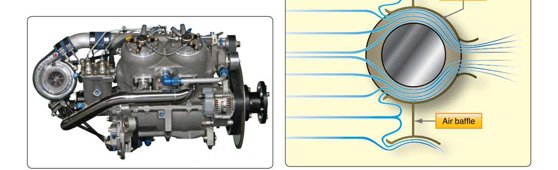
Unlike air-cooled engines that shed heat directly into the slipstream, liquid-cooled aircraft engines transfer combustion heat first to a circulating coolant and then to the outside air through a dedicated heat-exchange network. This two-step process allows tighter control of operating temperatures, more uniform cylinder temperatures, and reduced aerodynamic drag since cylinders can use a smooth cowling instead of extensive cooling fins — qualities prized in early high-performance warbirds and increasingly revisited in modern light sport and experimental designs. For the Aviation Maintenance Technician (AMT) seeking a Powerplant certificate, a thorough command of every component in this closed-loop system, how it functions, and how it can fail is both a knowledge-test requirement and a practical workplace necessity.
This article walks through each major component of a liquid-cooled aircraft engine cooling system in the sequence that coolant actually travels, then addresses why the system is engineered the way it is, key testable specifications, and the traps the FAA written examination commonly exploits.
The Closed-Loop Cooling Circuit: An Overview
A liquid-cooled system is a sealed, pressurized loop. Coolant — historically ethylene glycol or a glycol-water mixture — absorbs heat at the engine's water jackets, travels to a radiator where air removes that heat, and returns to the engine to repeat the cycle. Because the system is pressurized, the coolant can operate above its normal atmospheric boiling point, dramatically increasing the system's heat-carrying capacity without boiling. Every component described below plays a specific role in sustaining this cycle reliably across a wide range of power settings and ambient conditions.
Water Jackets and Cylinder Passages
The cooling process begins inside the engine itself. Each cylinder is surrounded by a water jacket — a network of cast or machined passages that enclose the cylinder barrel and head. Hot combustion gases transfer heat through the cylinder walls into the coolant circulating through these passages. The jacket design deliberately concentrates coolant flow around the hottest zones: the exhaust valve seat, the area between the exhaust and intake ports, and the top of the cylinder where peak combustion temperatures occur. Inadequate jacket flow in these areas leads to localized overheating, detonation, and eventually warped or cracked cylinder heads — which is why jacket integrity is the first thing an AMT inspects after any overheat event.
The Water Pump
A centrifugal water pump, driven mechanically from the engine's accessory section (or sometimes by a belt from the crankshaft), forces coolant through the entire circuit. Centrifugal pumps are preferred because their output flow increases with engine RPM — exactly when the engine is producing more heat and needs more cooling. The pump housing includes an inlet port that draws cool coolant returning from the radiator and an outlet port that pushes it into the engine's water jackets under pressure. Cavitation can develop when local pressure at the pump inlet drops below the coolant's vapor pressure — for example, due to a restriction, insufficient flow, or high pump speed — causing vapor bubbles to form and then implode against the impeller as they reach higher-pressure regions; this can erode impeller surfaces over time. AMTs should always consult the manufacturer's maintenance manual for the specific failure modes and inspection criteria applicable to a given pump, and should check for weeping coolant at the pump's telltale drain hole, which signals seal deterioration before a catastrophic leak develops.
Coolant and Coolant Selection
The coolant itself is an engineered fluid, not plain water. Aircraft liquid-cooled engines historically used ethylene glycol or a 70/30 mixture of ethylene glycol and distilled water. The glycol raises the boiling point and lowers the freezing point compared to water alone, while also providing corrosion inhibition for the aluminum, steel, and copper alloys inside the system. Some modern installations specify propylene glycol-based coolants for lower toxicity. An AMT must always verify the approved coolant type specified in the engine manufacturer's Type Certificate Data Sheet (TCDS) or maintenance manual before servicing — mixing incompatible coolant chemistries can precipitate sludge that clogs narrow passages and destroys seals.
The Thermostat
The thermostat is a temperature-sensitive bypass valve positioned in the coolant outlet passage of the engine. Its purpose is to maintain coolant temperature within a narrow operating band during all phases of flight and ground operation. When the engine is cold, the thermostat remains closed, routing coolant through a short bypass circuit that keeps it circulating inside the engine without passing through the radiator. This allows the engine to warm up quickly to its optimal operating temperature, reducing cylinder wear and improving combustion efficiency. Once coolant temperature reaches the thermostat's rated opening temperature — typically in the range the manufacturer specifies, often around 160°F to 180°F for many designs — the thermostat progressively opens, diverting increasingly more flow through the radiator. A stuck-closed thermostat causes rapid overheating in cruise; a stuck-open thermostat prevents the engine from reaching normal operating temperature, increasing wear and allowing fuel condensation in the oil. Both failures are detectable by monitoring coolant temperature gauges.
The Radiator
The radiator (sometimes called a heat exchanger or cooler) is where heat moves from the coolant into the airstream. Aircraft radiators are constructed from a core of narrow tubes or passages bonded between thin aluminum or copper fins. Hot coolant flows through the tubes; ram air (and, in some installations, air drawn by a dedicated fan) flows across the fins. The large surface area created by the fins dramatically accelerates heat transfer by convection. Aircraft radiators are typically mounted in a dedicated duct or scoop — often under the fuselage, in a wing root, or in the engine cowling — designed to manage airflow efficiently. A shutter or flap system (discussed next) controls how much air passes through the core.
Radiator cores are vulnerable to impact damage from debris and to internal clogging from scale, corrosion products, or contaminated coolant. An AMT inspecting a radiator should pressure-test the core to the manufacturer's specification and visually inspect for fin damage, leaks at tank-to-core joints, and signs of previous repairs. Even a small coolant leak at the radiator will progressively deplete the system, and in flight, a rapid coolant loss can lead to engine seizure within minutes.
Radiator Shutters and Cooling Flaps
Because airflow and engine heat output vary enormously between takeoff, climb, cruise, and descent, liquid-cooled aircraft engines use adjustable radiator shutters or cooling gills to modulate airflow through the radiator core. These louver-type panels are operated by the pilot from the cockpit, either manually with a lever or automatically via a thermostatic actuator. Opening the shutters increases cooling; closing them reduces drag and allows the engine to warm up faster. Improper use — leaving shutters closed at high power — is a well-documented cause of overheating, particularly during extended climbs. AMTs must verify that shutter linkages move freely through their full range, that actuator mechanisms (electric or hydraulic) respond correctly, and that the shutters fully seal when closed to prevent unnecessary drag in cruise.
The Expansion Tank and Overflow Reservoir
Pressurizing the cooling system raises the boiling point of the coolant mixture and accommodates the volumetric expansion of fluid as it heats up. The expansion tank (also called a header tank or surge tank) serves as the high point of the system, providing a small air/vapor space above the coolant. Any vapor that forms elsewhere migrates to this tank rather than accumulating in the water jackets or pump inlet where it could cause cavitation or hot spots. The pressure cap on the expansion tank is calibrated to a specific pressure rating (commonly 7 to 15 psi for various aircraft systems, per manufacturer data); it contains both a pressure relief valve — which opens to vent excess pressure — and a vacuum valve — which allows atmospheric air to enter as the system cools and coolant contracts, preventing hose collapse. An AMT should always pressure-test the cap during scheduled maintenance and never open the cap on a hot system, as pressurized boiling coolant can cause severe burns.
The overflow reservoir is a small separate bottle connected to the expansion tank's overflow outlet. If system pressure exceeds the cap's rating, coolant vents into this reservoir rather than overboard. As the engine cools, the system draws that coolant back in, keeping the primary circuit full. A chronically low overflow reservoir indicates a system leak or a faulty pressure cap allowing excessive pressure buildup.
Hoses, Clamps, and Plumbing
Flexible coolant hoses connect the rigid components, accommodating engine vibration and relative movement. Aircraft-quality hoses are reinforced with braided layers to withstand system pressure and high temperatures. AMTs inspect hoses for exterior cracking, swelling, softness (indicating internal deterioration), and security of clamps. Hose clamps must be tightened to the manufacturer's specified torque — overtightening cuts the hose material; undertightening allows leaks under pressure.
Why the System Design Matters for Safety
The pressurized, closed-loop architecture of the liquid-cooling system is not accidental — it is an engineering solution to the fundamental challenge that aircraft engines produce enormous heat in a compact, weight-limited package. Every component is interdependent: a failed water pump starves the jackets; a stuck thermostat prevents temperature regulation; a damaged radiator bleeds the system dry. Unlike an air-cooled engine where a cracked fin is usually a non-event, a single failed hose in a liquid-cooled system can force an immediate off-airport landing. This interconnectedness means that thorough preflight inspection of visible coolant lines, monitoring of cockpit temperature gauges, and adherence to manufacturer maintenance intervals are genuinely life-safety issues, not bureaucratic formalities.
Key Numbers and Rules
- Coolant type: Always verify against the TCDS and maintenance manual — mixing incompatible coolants creates corrosive sludge.
- Pressure cap rating: Typically 7–15 psi depending on the specific aircraft system; always test the cap during scheduled service.
- Thermostat opening range: Usually begins opening around 160°F–180°F (exact value is model-specific); verify with manufacturer data.
- Centrifugal pump flow: Increases proportionally with engine RPM, providing greater cooling at higher power settings automatically.
- Radiator pressure test: Perform to the manufacturer's specified pressure; even small leaks become large leaks under flight vibration and thermal cycling.
- System inspection trigger: Any coolant loss, overheating event, or abnormal temperature indication requires a full system inspection before return to service.
Common Test Traps
- Thermostat failure mode confusion: The FAA exam often tests whether students know that a stuck-closed thermostat causes overheating (no flow to radiator), while a stuck-open thermostat causes under-temperature operation — students frequently reverse these.
- Pressure cap vacuum valve: Many students forget the cap has TWO valves — one for overpressure relief and one vacuum valve to prevent hose collapse on cool-down. Questions may ask specifically about the vacuum valve function.
- Coolant vs. water: Pure water is never the correct answer for aircraft liquid-cooling systems; the glycol mixture is required for both freezing protection and corrosion inhibition.
- Centrifugal pump characteristics: The exam may ask why a centrifugal pump is used; the correct answer relates to flow increasing with RPM to match higher heat output, not simply that it is lighter or cheaper.
- Overflow reservoir purpose: Students sometimes confuse this with the expansion tank. The overflow reservoir catches coolant vented by the pressure cap and returns it to the system — it does not pressurize the system or serve as the main vapor separator.