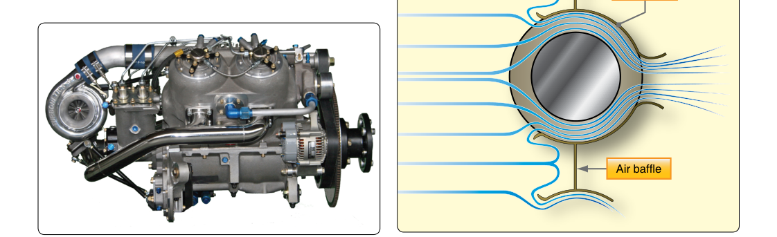
In an air-cooled aircraft engine, there is no radiator, no coolant jacket, and no water pump to carry heat away from the combustion chamber. Instead, every British Thermal Unit (BTU) of excess heat must travel through metal and leap into moving air. The engineering solution is the cooling fin — a carefully shaped, precisely sized aluminum or steel projection cast or machined into the outer surface of each cylinder barrel and cylinder head. Understanding how these fins work, why they are designed the way they are, and what happens when they are damaged or obstructed is essential knowledge for every Aviation Maintenance Technician (AMT) working on powerplant systems.
This article covers fin geometry, heat transfer physics, airflow management, inspection standards, and the specific rules and numbers that appear on the FAA AMT Powerplant knowledge test.
The Physics of Heat Rejection in Air-Cooled Cylinders
Combustion in a typical aircraft cylinder generates gas temperatures that can exceed 4,000 °F at peak pressure. The cylinder walls, crown, and head must absorb this energy continuously and reject it before metal temperatures climb to the point where strength is compromised, oil burns off, and pre-ignition or detonation becomes uncontrollable. The FAA Powerplant Handbook (FAA-H-8083-32) explains that cylinder head temperatures (CHT) in normally aspirated engines are generally kept below manufacturer limits — often around 400–500 °F depending on the engine — through proper fin design, baffling, and airflow.
Heat moves from the combustion gases into the cylinder walls by convection and radiation. It then conducts through the cylinder metal and finally passes from the fin surface into the air by forced convection. The rate at which heat leaves the fin surface depends on three factors: surface area, temperature differential between the fin and the passing air, and airflow velocity across the fin. Fin design directly controls two of these three factors — surface area and, indirectly, local airflow velocity through fin spacing.
Fin Geometry: Shape, Spacing, and Material
Aircraft engine cooling fins are not simply flat plates welded onto a cylinder. They are precisely engineered features whose geometry reflects a careful balance of competing demands.
Fin Depth and Thickness
A deeper (taller) fin exposes more surface area to the airstream and therefore rejects more heat per unit of cylinder surface. However, a fin that is too deep without adequate thickness at its base will be structurally weak, prone to cracking under vibration, and may actually impede airflow to the fins behind it by creating turbulence or stagnation zones. Most aircraft cylinder fins taper from a thicker base — where they must transmit stress without cracking — to a thinner tip where area-to-mass ratio is maximized. Typical fin depths range from less than half an inch on barrel fins to over an inch on cylinder head fins, where heat rejection demands are highest because that is where combustion gases are hottest.
Fin Spacing
The gaps between fins must be wide enough to allow adequate airflow but narrow enough to keep the number of fins — and therefore total surface area — high within a given cylinder length. If fins are spaced too closely, viscous drag slows the airstream deep in the inter-fin channel before it can carry heat away effectively. If spaced too far apart, fewer fins mean less total surface area. Engineers optimize this spacing based on expected air velocity through the cowling and the thermal conductivity of the fin material. On most horizontally opposed and radial engines, fin spacing is typically measured in fins per inch, and this figure is controlled to fine tolerances during manufacture.
Cylinder Barrel vs. Cylinder Head Fins
Cylinder barrels (the steel portion housing the piston) have fins that are smaller and more uniform than head fins. The barrel runs cooler than the head, and its fins are often machined in a lathe-turning operation, producing a consistent helical or annular pattern. Cylinder heads are usually cast from an aluminum alloy — a material with roughly four times the thermal conductivity of steel — which allows fins to be cast in complex shapes that follow the curves of intake and exhaust ports, valve bosses, and spark plug bosses. The head fins are larger, more closely spaced in critical areas near the exhaust valve, and often irregular in shape to maximize cooling exactly where it is needed most. The exhaust valve area of the head is the hottest region in the entire cylinder assembly and typically receives the deepest, most tightly spaced fins.
Baffles, Blast Tubes, and Airflow Management
Cooling fins do their job only when air actually moves across them at sufficient velocity. In a cowled aircraft engine, ram air from forward flight is not automatically directed evenly across every fin of every cylinder. Without proper baffling, air follows the path of least resistance, cooling some cylinders adequately while starving others. The engine baffles — sheet metal or composite panels that seal the gaps between cylinders, between cylinders and the cowling, and around the accessory case — create a high-pressure plenum above the cylinders and a low-pressure region below. This pressure differential drives cooling air down through the inter-fin spaces and around each cylinder in a controlled, uniform pattern.
Blast tubes are small directed tubes that channel a jet of cooling air specifically toward the exhaust valve area of each cylinder head, supplementing the general airflow where temperatures are most extreme. Seals made of rubber or silicone close gaps between baffles and the cowling to prevent pressure equalization that would reduce flow. The FAA Powerplant Handbook emphasizes that damaged, missing, or improperly fitted baffles are a leading maintenance-related cause of excessive CHT, and that every baffle seal must be inspected and replaced if cracked, compressed, or hardened.
Why Fin Integrity Is a Safety Issue
A single cracked or missing fin does not immediately destroy an engine, but it represents a structural defect that can propagate and a cooling deficit that accumulates. When a fin is broken away, the surface area available for heat rejection in that local region is reduced. The cylinder metal beneath the missing fin runs hotter, thermal gradients between adjacent areas increase, and the risk of crack propagation in the head or barrel increases. Detonation — the uncontrolled explosive combustion of the fuel-air mixture — is more likely in an overheated cylinder and can destroy a piston, connecting rod, or cylinder in seconds.
Beyond cracking, fins can be damaged by improper cleaning with wire brushes or abrasive tools, by wrench or tool strikes during maintenance, by exhaust gases if an exhaust stack fails, or by impact from foreign objects. Any of these damage modes must be identified during inspection and evaluated against manufacturer and FAA limits before the aircraft is returned to service.
Key Numbers, Rules, and Inspection Standards
- Fin damage limits: Manufacturers publish specific limits on how much of a fin may be missing before the cylinder must be replaced or repaired. A common industry standard, referenced in FAA guidance, allows minor damage — typically not exceeding a certain percentage of fin area or a specific depth of crack — to be blended smooth to prevent further cracking, provided no sharp notches remain that would act as stress concentrators.
- Cylinder head temperature (CHT) limits: Always defer to the specific engine manufacturer's Type Certificate Data Sheet (TCDS) and operating limitations. Many air-cooled engines have CHT limits in the 400–500 °F (approximately 205–260 °C) range for continuous operation, with higher transient limits sometimes permitted for brief periods.
- Baffle seal inspection: Baffle seals should be inspected at every annual inspection and at 100-hour intervals under 14 CFR Part 43 standards. Seals that are cracked, torn, or have lost their resilience must be replaced.
- Material: Cylinder barrels are typically steel (chrome- or nitrided steel); cylinder heads are aluminum alloy. Dissimilar-metal thermal expansion differences between the steel barrel and aluminum head are accounted for in the thread-fit design of cylinder assemblies.
- Heat transfer principle: The greater the temperature differential between the fin surface and the cooling air, the faster heat is rejected. This is why leaning the mixture to run the engine hotter in cruise is a careful balance — hotter fins reject heat faster per unit area, but if CHT limits are approached, the margin to detonation shrinks.
- Fin cleaning: Fins must be cleaned carefully using soft brushes or compressed air; never use wire brushes that could scratch, notch, or create stress risers in the fin material.
Common Test Traps
- Confusing barrel and head materials: The FAA test may ask about fin material. Remember — steel barrels, aluminum alloy heads. Aluminum's high thermal conductivity is why the head can use fins as its primary cooling path despite absorbing the most heat.
- Assuming damaged fins are always cause for rejection: Not every damaged fin grounds the aircraft. The key is comparing measured damage against the manufacturer's published limits. Knowing that limits exist — and that minor damage can sometimes be blended — is the testable point.
- Overlooking baffles in CHT problems: Test questions about high CHT often have a baffling deficiency as the correct answer. Missing or deteriorated baffles can cause dangerously high temperatures even when the fins themselves are in perfect condition.
- Misidentifying the hottest cylinder region: The exhaust valve area of the cylinder head — not the center of the piston crown or the barrel midpoint — is typically the hottest region and therefore has the most aggressive fin design. Test questions may probe whether you know this.
- Ignoring fin spacing as a design variable: Students sometimes think only fin depth matters. In fact, fin spacing (the channel width) is equally important because it controls inter-fin airflow velocity and turbulence. Both depth and spacing are engineered together.