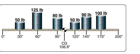
Weight and balance is not merely a paperwork exercise — it is a fundamental safety calculation that determines whether an aircraft will fly predictably and stay within its structural design limits. At the heart of every weight and balance calculation are three interrelated values: weight, arm, and moment. Understanding how these three quantities work together, and how to use them to find the center of gravity (CG), is one of the most important skills an Aviation Maintenance Technician (AMT) must master. It is heavily tested on the FAA AMT General knowledge exam, and errors in real-world practice have contributed to fatal accidents.
This article walks through the underlying physics, the step-by-step calculation method, and the common traps that trip up both test-takers and working technicians.
The Fundamental Relationship: Weight, Arm, and Moment
Every weight and balance calculation begins with three defined terms. Weight is simply the force of gravity acting on a mass, expressed in pounds. Arm is the horizontal distance, measured in inches, from a fixed reference point called the datum to the location where a given weight acts (its center of gravity). Moment is the product of weight multiplied by arm — it is a measure of the rotational tendency that a particular weight creates around the datum. Moment is expressed in inch-pounds (in-lb).
The governing formula is straightforward:
Moment (in-lb) = Weight (lb) × Arm (in)
And rearranged, CG is found by dividing the total moment by the total weight:
CG Location (in) = Total Moment (in-lb) ÷ Total Weight (lb)
The result tells you exactly how many inches from the datum the combined center of gravity of the entire loaded aircraft falls. If that location falls within the manufacturer's specified forward and aft CG limits, the aircraft is within its approved envelope.
The Datum: The Starting Point for All Measurements
The datum is an imaginary vertical plane from which all horizontal arm measurements are taken. The manufacturer selects the datum location and publishes it in the aircraft's Type Certificate Data Sheet (TCDS) and Weight and Balance report. Common datum locations include the leading edge of the wing, the firewall, the nose of the aircraft, or even a point ahead of the aircraft nose. The exact location does not matter mathematically — what matters is that every arm in the calculation is measured consistently from that same reference point.
When the datum is located at or within the aircraft (such as the firewall or wing leading edge), arms measured aft of the datum are typically assigned positive (+) values, and arms measured forward of the datum are assigned negative (−) values. However, many manufacturers instead place the datum at a point ahead of the entire aircraft (such as the nose or spinner), which makes every arm on the aircraft positive and eliminates the need for negative numbers in the calculation. Either convention is acceptable — what matters is that whichever convention is used, it is applied consistently, since if you add weight ahead of the datum, its moment shifts the total CG forward, and if you add weight aft of the datum, its moment shifts the CG aft. Getting the signs wrong (when a signed convention is used) is one of the most common sources of calculation errors.
Step-by-Step: Calculating CG for a Loaded Aircraft
The standard method uses a loading schedule or weight and balance table with columns for item, weight, arm, and moment. Here is the procedure:
- List every item contributing to the loaded weight. This includes the aircraft's Basic Empty Weight (BEW), each occupant, baggage, cargo, and usable fuel. The BEW and its CG arm (along with the resulting moment) are taken directly from the aircraft's official weight and balance records — never estimated.
- Assign each item its arm. Occupant arm positions, baggage compartment arms, and fuel tank arms are all published in the aircraft flight manual or weight and balance documentation.
- Calculate the moment for each item. Multiply weight × arm for every line.
- Sum the weights. Add all individual weights to get Total Loaded Weight (also called Gross Weight).
- Sum the moments. Add all individual moments, observing algebraic sign, to get Total Moment.
- Divide Total Moment by Total Weight. The quotient is the CG location in inches from the datum.
- Compare to limits. Check whether the computed CG falls within the forward and aft CG limits published for that gross weight. Both the weight AND the CG must be within limits simultaneously.
Worked Example
Suppose a small aircraft has the following loading for a flight (all arms measured from a firewall datum, so all values are positive):
- Basic Empty Weight: 1,450 lb at arm 39.0 in → Moment: 56,550 in-lb
- Pilot and front passenger: 340 lb at arm 37.0 in → Moment: 12,580 in-lb
- Rear passengers: 300 lb at arm 73.0 in → Moment: 21,900 in-lb
- Baggage: 50 lb at arm 95.0 in → Moment: 4,750 in-lb
- Fuel (30 gal × 6 lb/gal = 180 lb): arm 48.0 in → Moment: 8,640 in-lb
Total Weight: 1,450 + 340 + 300 + 50 + 180 = 2,320 lb
Total Moment: 56,550 + 12,580 + 21,900 + 4,750 + 8,640 = 104,420 in-lb
CG Location: 104,420 ÷ 2,320 = 45.01 inches aft of datum
If the aircraft's allowable CG range at 2,320 lb is, say, 35.0 to 47.5 inches aft of the datum, this loading is within limits. The technician would also verify that 2,320 lb does not exceed the published maximum gross weight.
How Fuel Burn Shifts CG
One often-overlooked aspect of weight and balance is that CG is not static during flight — it changes as fuel is consumed. Because fuel tanks are rarely located exactly at the aircraft's CG, burning fuel removes weight at a specific arm, causing the CG to move. Fuel located aft of the CG will cause the CG to move forward as that fuel burns; fuel located forward of the CG will cause the CG to move aft. A prudent AMT or pilot checks the CG at maximum fuel load, at zero fuel (or minimum fuel), and at critical points in between to confirm the aircraft remains within its CG envelope throughout the entire flight.
Moment Indexes and Reduction Factors
Because moment values can become very large numbers that are prone to arithmetic error, aircraft manufacturers sometimes use a moment index — a simplified number derived by dividing the actual moment by a constant reduction factor (such as 100 or 1,000). The Weight and Balance Handbook (FAA-H-8083-1) explains this technique. When using moment indexes, the same reduction factor must be applied consistently to every item in the table; the final CG is then computed the same way using reduced moments and the same reduction factor cancels algebraically. Always check whether the manufacturer's documentation uses actual moments or reduced indexes before beginning calculations.
Why It Matters: Safety and Airworthiness
An aircraft loaded outside its CG envelope is a serious airworthiness concern even if it is under maximum gross weight. A CG that is too far forward increases the load on the tail, demands more up-elevator to maintain level flight, raises stall speed, and can make the aircraft impossible to rotate on takeoff. A CG that is too far aft reduces longitudinal stability — in the extreme, the aircraft may become uncontrollable because the pilot cannot generate enough nose-down pitch force to recover from an upset. The structural design of the aircraft also assumes loads will fall within defined limits, so an out-of-CG condition can impose stresses the airframe was never designed to handle.
Key Numbers and Rules
- Moment = Weight × Arm — the single most important formula.
- CG = Total Moment ÷ Total Weight — always divide by weight, never the other way around.
- Positive arms are typically aft of the datum; negative arms are forward of the datum (unless the datum is placed ahead of the entire aircraft, in which case all arms are positive).
- Avgas weighs approximately 6 lb/gal; jet fuel (Jet-A) weighs approximately 6.7 to 6.8 lb/gal depending on temperature and the reference used — know the value given in the applicable aircraft documentation.
- Oil weighs approximately 7.5 lb/gal (roughly 1.875 lb per quart, though some FAA reference tables use slightly different values, so always check the specific handbook or aircraft weight and balance data for the figure used).
- Both weight AND CG must be within limits — satisfying one condition without the other does not make the aircraft airworthy.
- The Basic Empty Weight includes the airframe, engine, all permanently installed equipment, unusable fuel, and full operating fluids (except usable fuel). Always start a weight and balance calculation from the current, FAA-approved BEW record.
Common Test Traps
- Forgetting to include oil or unusable fuel. The FAA exam may provide a scenario where students confuse usable and unusable fuel. Unusable fuel is already included in BEW; usable fuel must be added as a separate line item.
- Mixing up arm signs. If the datum is at the nose and a weight is placed forward of the nose (an unusual but possible scenario), that arm is negative and produces a negative moment. Failing to apply the minus sign will shift your calculated CG aft of reality.
- Dividing moment by arm instead of by weight. The formula is CG = Total Moment ÷ Total Weight. Reversing the divisor and dividend produces a nonsensical result but looks plausible to a test-taker in a hurry.
- Not checking the CG at the zero-fuel or low-fuel condition. The aircraft may be within CG limits at full fuel but shift out of limits as fuel burns — the exam tests awareness that CG must remain in limits throughout the flight envelope.
- Using an outdated Basic Empty Weight. Whenever equipment is added or removed, a new BEW must be computed and the old record superseded. Using an old BEW with a new piece of avionics not accounted for invalidates the entire calculation.