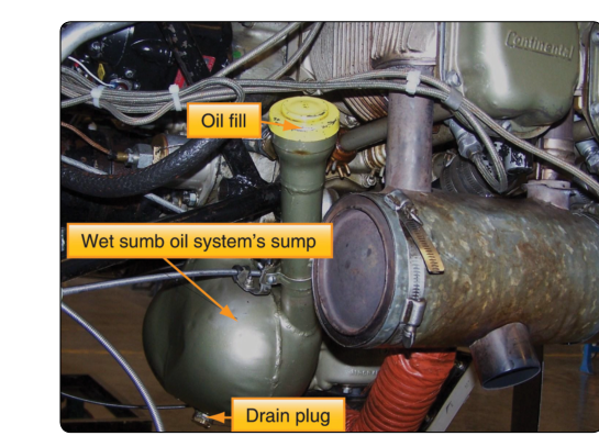
Every reciprocating aircraft engine depends on a continuous, pressurized supply of oil to prevent metal-to-metal contact between moving parts, carry away heat, clean internal passages, and cushion bearing loads. The two fundamental designs used to accomplish this are the wet-sump system and the dry-sump system. Understanding the differences between them — how each is built, why each exists, and where each belongs — is essential knowledge for any Aviation Maintenance Technician (AMT) working on powerplants, and it is a subject the FAA Powerplant knowledge test examines directly.
The names themselves tell the story: in a wet-sump engine the oil reservoir is the engine sump (the bottom of the crankcase), so the sump stays "wet" with a pool of stored oil. In a dry-sump engine, oil is scavenged out of the crankcase almost as fast as it drains there and returned to a separate, external tank, so the crankcase sump remains essentially "dry" during operation.
How the Wet-Sump System Works
The wet-sump is the simpler of the two designs. A relatively large crankcase sump at the bottom of the engine holds the entire oil supply — capacity varies by model, with light single-engine aircraft engines such as the Lycoming O-360 and Continental O-300 typically holding around eight quarts, while smaller engines such as the Continental O-200 may hold as little as six quarts. A single gear-type or gerotor pressure pump, driven from the accessory section of the engine, draws oil from the sump through a screen or filter, pressurizes it, and forces it through drillings and galleries to the crankshaft main bearings, connecting-rod bearings, camshaft bearings, and other lubricated surfaces. After doing its work, the oil drains by gravity back into the sump, ready to be recirculated.
Because the oil lives inside the engine, the wet-sump design requires fewer external components: no separate tank, no scavenge pump, no external oil lines running between tank and engine. This simplicity translates to lower weight, lower cost, and easier maintenance — advantages that make the wet-sump the standard choice for most horizontally opposed, air-cooled engines powering light general aviation aircraft.
The wet-sump system does, however, have one important limitation: attitude sensitivity. If the aircraft is placed in a steep nose-high, nose-low, or inverted attitude for more than a brief moment, the oil in the sump can uncover the pump inlet (suction screen), allowing the pump to draw air instead of oil. The result is an immediate and potentially catastrophic loss of oil pressure. This makes the basic wet-sump design unsuitable for sustained inverted flight or aggressive aerobatics.
How the Dry-Sump System Works
The dry-sump system solves the attitude problem by removing the oil reservoir from the engine entirely. Oil is stored in a dedicated external tank — typically a hopper-style or baffled aluminum tank mounted in the airframe near the engine. From this tank, a pressure pump (also called the supply pump) draws oil, pressurizes it, and delivers it to the engine bearings and other components, just as in a wet-sump system.
The key addition is one or more scavenge pumps. These pumps — usually gear-type, often incorporated into the same pump body as the pressure pump but with larger capacity — continuously pull oil out of the engine sump and return it to the external tank. Because the scavenge pumps have a greater total capacity than the pressure pump, the sump never accumulates a significant reservoir of oil; it stays effectively dry. The extra capacity of the scavenge section is intentional: it must handle not only oil but also the air-oil mixture (foam) and blow-by gases present in the crankcase.
Before the scavenged oil re-enters the tank, it typically passes through an oil cooler to reject heat accumulated during its circuit through the engine. A thermostatic bypass valve prevents the oil from being chilled excessively during cold starts. The external tank is vented to the crankcase to maintain pressure balance, and many designs incorporate a de-aerator or hopper to separate entrained air bubbles from the oil before it is re-pressurized.
Dry-sump systems are standard on most large radial engines (such as the Pratt & Whitney R-1340 and Wright R-1820) that powered classic transport and military aircraft, as well as on modern aerobatic and unlimited-category competition aircraft. Many helicopter turboshaft and other turbine powerplants also rely on a separate oil supply and scavenge arrangement conceptually similar to the dry-sump principle, though a number of turboshaft and turbine designs instead use a self-contained, integrated oil system rather than a true external dry-sump tank — the specific architecture varies by engine design and should not be assumed.
Why It Matters: Choosing the Right System
The decision between wet and dry sump is not arbitrary — it follows directly from how the aircraft will be operated and from the physical architecture of the engine.
Aerobatic and inverted flight: Any aircraft certificated for sustained inverted or aerobatic maneuvers requires either a dry-sump system or a specially modified wet-sump system that includes an inverted oil and fuel system (such as those found on some Lycoming AEIO-series engines using an oil accumulator and check valves). Without such provisions, even a few seconds of inverted flight can cause oil pressure to drop to zero, which will score bearings and can destroy an engine in less than a minute.
Large radial engines: Radial engine cylinders are arranged in a circle around the crankshaft. The lower cylinders sit below the crankcase centerline, and gravity naturally allows oil to seep past piston rings into those lower cylinders when the engine is not running. If sufficient oil accumulates, a hydraulic lock can occur when the starter is engaged — the incompressible oil prevents the piston from completing its stroke, bending connecting rods. The dry-sump design, by keeping the crankcase relatively empty of standing oil, reduces (though does not completely eliminate) this risk. Proper pre-oiling procedures are still required.
Cooling efficiency: By routing oil through an external tank and cooler, the dry-sump system provides far greater heat-rejection capacity. High-performance and turbocharged engines generate considerably more heat in their oil than a small naturally aspirated engine, making the external cooler circuit essential to maintaining safe oil temperatures.
Key Numbers and Rules
- Oil pressure: Typical reciprocating engine oil pressure limits generally fall in a range of roughly 25–60 psi at idle minimums up to around 60–90 psi at normal operating maximums, with the exact figures published in the engine Type Certificate Data Sheet and the manufacturer's operating handbook. Always consult the applicable publication.
- Scavenge pump capacity: In a dry-sump system, scavenge pump(s) are designed with a higher volumetric capacity than the pressure pump — commonly cited as roughly twice the pressure pump's capacity or more — to ensure the crankcase is kept dry under all operating conditions including foamy, aerated oil.
- Oil consumption monitoring: Tracking oil consumption is a recommended maintenance practice under general airworthiness standards (14 CFR 91.7 and 43.13) and manufacturer guidance, rather than a distinct regulatory mandate. High oil consumption in a wet-sump engine often points to worn rings or seals; in a dry-sump system, an external leak may also be the culprit given the greater number of external connections.
- Magnetic chip detectors: Many dry-sump systems incorporate magnetic chip detectors in the scavenge lines or external tank to catch ferrous metal particles — an early warning of internal bearing or gear wear.
- Oil grade and type: Whether wet or dry sump, the correct oil specification (ashless dispersant, straight mineral, or synthetic) must match the engine manufacturer's requirements, especially during the engine break-in period when straight mineral oil is typically mandated.
Component Summary: Wet vs. Dry at a Glance
The wet-sump system consists of: a sump integral to the crankcase, a single pressure pump, an oil pressure relief valve, a filter or screen, an oil temperature sensor, and an oil cooler (on some models). The dry-sump system adds: a separate external oil tank, one or more scavenge pumps (usually combined with the pressure pump in a single assembly), external oil lines between the tank and engine, a dedicated oil cooler with thermostatic bypass, and often a de-aerator in the tank. The greater complexity of the dry-sump system requires more rigorous inspection of all external fittings, hoses, and connections during each maintenance visit.
Common Test Traps
- Confusing pump roles: Students sometimes think the scavenge pump supplies oil to the bearings. It does the opposite — it removes oil from the sump back to the tank. The pressure pump is the one that supplies oil to lubricated surfaces.
- Assuming all aerobatic engines use dry sumps: Some aerobatic-certified engines use a wet sump modified with accumulators, check valves, and inverted oil pickup tubes. Always identify the specific system installed rather than assuming.
- Forgetting scavenge pump oversizing: The FAA test sometimes asks why the scavenge pump capacity exceeds the pressure pump capacity. The answer is that it must handle oil plus entrained air and crankcase gases, not just liquid oil.
- Hydraulic lock and radial engines: Questions about radial engine pre-start checks often hinge on the risk of hydraulic lock from oil accumulation in lower cylinders — a problem reduced (but not eliminated) by the dry-sump design.
- Oil cooler placement: In a dry-sump system the oil cooler is in the scavenge (return) circuit between the engine and tank, not between the tank and the pressure pump. Oil is cooled after leaving the engine, then stored in the tank at a lower temperature ready for re-use.