Of all the threats to a reciprocating engine's reliable operation, carburetor icing stands out because it can develop with startling speed under conditions that seem perfectly benign. Temperatures well above freezing, clear skies, and moderate humidity — these are not conditions most pilots or mechanics associate with ice, yet they are precisely the conditions under which carburetor ice thrives. For an Aviation Maintenance Technician (AMT) working on powerplant systems, a thorough understanding of why and how carburetor ice forms, how the alternate air system is designed to defeat it, and how to inspect and maintain these systems is not optional — it is foundational.
This article covers the physical mechanisms of carburetor icing, the three recognized types of carburetor ice, the design and function of carburetor heat and alternate air systems, the maintenance and inspection requirements that keep these systems airworthy, and the exam-critical facts every AMT candidate must know.
The Physics Behind Carburetor Icing
A float-type carburetor meters fuel and air by creating a pressure drop at the venturi and the throttle valve. This pressure drop is accompanied by a dramatic temperature drop, governed by the principles of thermodynamics. As air accelerates through the venturi, its pressure falls, and that pressure decrease causes a corresponding drop in air temperature — by as much as 60°F to 70°F within the carburetor throat under some conditions, per FAA guidance. When fuel is introduced and vaporizes, it absorbs additional latent heat from the surrounding air, potentially dropping local temperatures another 10°F to 15°F. The combined cooling effect can easily push the temperature inside the carburetor bore well below the freezing point of water (32°F / 0°C), even when the outside air temperature is in the 60s°F or higher.
Water vapor present in the incoming air then freezes on the interior surfaces of the carburetor — particularly around the throttle valve, the venturi, and the fuel discharge nozzle. This ice restricts airflow, leans or disrupts the fuel-air mixture, and if allowed to accumulate, can completely block the induction system and cause engine failure. Critically, the entire process can occur without any ice visible externally on the airframe.
Three Types of Carburetor Ice
The FAA recognizes three distinct types of carburetor icing, each with a different mechanism:
- Throttle ice (throttle body ice): Forms directly on and around the throttle valve. The pressure drop at a partially closed throttle is especially pronounced, causing rapid local cooling. This type is most likely at low power settings and is often the first kind to appear during descent or approach.
- Fuel evaporation ice (evaporation ice): Results from the cooling effect of fuel vaporization. Even in very dry air, the latent heat absorbed during fuel atomization can be enough to cause ice formation at the fuel discharge nozzle. This type can occur at a wider range of ambient temperatures and humidity levels than many technicians expect.
- Impact ice: Occurs when supercooled water droplets or wet snow in the atmosphere are ingested and freeze on contact with carburetor inlet surfaces or the air filter. Unlike the other two types, impact ice is most likely at or near freezing temperatures in visible moisture — classic icing conditions — and generally requires visible precipitation or cloud entry.
Most Dangerous Conditions for Carburetor Icing
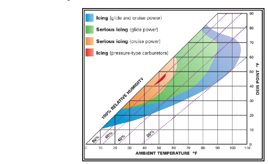
According to the FAA's carburetor icing probability chart (FAA-H-8083-25, Chapter 7), the most dangerous ambient conditions for fuel evaporation and throttle icing span roughly 20°F to 90°F (approximately -7°C to 32°C) combined with relative humidity above 50-60%. The sweet spot of maximum risk is often cited around 32°F to 50°F with high humidity — but the FAA icing probability chart shows serious icing risk at glide power extending up to approximately 100°F when humidity is very high. AMTs must communicate this counterintuitive fact clearly when educating pilots and during sign-off discussions: carburetor icing is not just a cold-weather problem.
The Carburetor Heat System
The primary defense against carburetor icing in most light aircraft reciprocating engines is the carburetor heat system. This system routes ram air through a shroud or muff surrounding the engine exhaust system, where the air is heated before being introduced into the carburetor. The heated air bypasses the normal induction air filter and enters through an alternate passage, raising the temperature inside the carburetor bore above the icing threshold.
Key design and operational characteristics of carburetor heat systems include:
- Unfiltered air: Because carb heat air bypasses the intake air filter, continuous use on the ground — especially during ground runup on dusty or contaminated surfaces — can ingest abrasive particles that damage engine internals. Carb heat is therefore used judiciously on the ground.
- Power reduction: Hot air is less dense than cold air. Applying carburetor heat always reduces manifold pressure and engine power output, typically by a small but measurable amount. On carbureted engines, this drop in RPM or manifold pressure is expected and normal when carb heat is applied.
- Mixture enrichment: Heated, less-dense air effectively enriches the fuel-air mixture. In severe icing conditions, the mixture may need to be leaned slightly after carb heat application to prevent rough running.
- Temporary roughness: When carb heat is applied to an already iced carburetor, the melting ice causes a brief period of rough running and possibly a further RPM drop as water passes through the engine. This is normal and expected — the roughness should clear as the ice melts. Failure to clear indicates either severe icing or another problem.
Alternate Air Systems on Fuel-Injected Engines
Fuel-injected engines do not use a carburetor venturi and therefore are not susceptible to carburetor ice. However, they are not immune to induction icing altogether. Fuel-injected engines can suffer induction system icing (impact ice) at the air intake screen or alternate air door. For these engines, the equivalent of carb heat is the alternate air door or alternate air valve.
On many fuel-injected installations, the alternate air door is spring-loaded to open automatically if the primary air intake becomes blocked by ice. This provides a fail-safe: even if a pilot does not manually select alternate air, the door opens when the pressure differential across a blocked intake becomes large enough to overcome the spring force. The alternate air source on fuel-injected engines typically draws warm air from inside the engine compartment (rather than a heated exhaust muff), which is generally above freezing due to engine heat radiation.
From a maintenance perspective, the AMT must verify that the alternate air door moves freely, the spring tension is within manufacturer specifications, and the sealing surfaces are intact so that normal (unheated) ram air is used during standard operations and filtered air is not bypassed unnecessarily.
Inspection and Maintenance of Carburetor Heat and Alternate Air Systems
Proper maintenance of these systems is critical to airworthiness. Key inspection points include:
- Exhaust muff integrity: Cracks or holes in the exhaust shroud used to heat carb heat air can allow carbon monoxide to enter the induction system — a potentially lethal contamination. The muff must be inspected thoroughly at each annual inspection and any time exhaust system work is performed.
- Carburetor heat control rigging: The control cable or linkage must move the heat valve to its full HEAT and full OFF positions. Partial travel means incomplete heating or unintended air leaks.
- Air filter condition: The primary induction air filter should be inspected for blockage, damage, or collapse. A collapsed filter can mimic carburetor icing symptoms by restricting airflow.
- Alternate air door seals and hinge: On fuel-injected engines, the alternate air door must seal properly when closed and open fully and freely when actuated. Check the hinge pin, door stops, and sealing gasket per the Aircraft Maintenance Manual (AMM).
- Carb heat indicator: Some aircraft use a carburetor air temperature (CAT) gauge to give the pilot direct temperature feedback inside the carburetor throat. The AMT should verify the probe and indicator are functional during inspection.
Why It Matters: Safety and Airworthiness
Engine failure caused by carburetor icing has been a contributing factor in numerous general aviation accidents over the decades. Many of these accidents occurred during approach to landing — exactly when the throttle is partially closed and icing risk is highest — and in weather that the pilot did not associate with icing risk. A properly functioning carburetor heat or alternate air system, correctly maintained by a knowledgeable AMT, is a direct lifesaving system. An improperly rigged heat valve that only partially opens, or an exhaust muff with a crack that poisons the heated airflow, can be as dangerous as having no system at all.
Key Numbers and Rules
- Temperature drop inside carb venturi: up to 60°F to 70°F from pressure decrease, plus additional cooling from fuel evaporation.
- Highest icing risk ambient temperature range: approximately 20°F to 90°F (-7°C to 32°C) with relative humidity above 50-60%.
- Carb heat air is unfiltered — limit ground use to reduce abrasive ingestion.
- Applying carb heat always causes a decrease in power output due to lower air density.
- On fuel-injected engines, alternate air doors are commonly spring-loaded to open automatically on intake blockage.
- Exhaust muff cracks risk carbon monoxide contamination of carb heat air — inspect at every annual.
- Impact ice requires visible moisture near freezing; fuel evaporation and throttle ice can form in clear air with no precipitation.
Common Test Traps
- Carb ice only happens in cold weather. False — the most insidious carburetor icing (fuel evaporation and throttle types) occurs in warm, humid conditions, not just near-freezing temperatures.
- Fuel-injected engines are immune to all induction icing. False — they are immune to carburetor ice but can still experience impact ice at the air intake, which is why an alternate air system is still required.
- Roughness after carb heat application means the system isn't working. Actually, temporary roughness and an RPM dip are normal signs that ice is melting. The system IS working. The roughness should clear.
- Full-power settings are safe from carburetor icing. While the risk is reduced at full power (less throttle restriction), icing can still occur, especially from fuel evaporation, and pilots/technicians should not assume full power eliminates all risk.
- Carb heat air comes through the main air filter. False — carb heat bypasses the filter entirely, which is why ground use is limited and why a cracked exhaust muff is such a serious hazard.