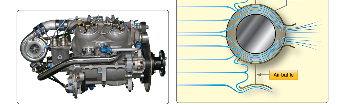
Reciprocating aircraft engines produce an enormous amount of heat as a byproduct of combustion. Unlike automobile engines, which rely primarily on liquid coolant circulating through a closed system, most certificated light aircraft engines are air-cooled — they depend entirely on moving air to carry heat away from the cylinders and other hot components. Left unmanaged, this heat would quickly destroy engine parts, warp cylinder heads, and seize pistons. The systems that channel, control, and optimize that cooling airflow — the cylinder baffling and cowl flaps — are therefore not accessories but life-support equipment for the engine. Every aviation maintenance technician (AMT) seeking a Powerplant certificate must understand how these systems work, why they fail, and how to inspect and maintain them properly.
This article covers the physics behind air-cooled engine cooling, the design and function of baffling and cowl flap systems, the inspection standards applied to each, and the test-relevant details you need to know for the FAA Powerplant knowledge exam.
How Air-Cooled Engines Lose Heat
During the power stroke, combustion gas temperatures inside a cylinder are commonly cited in the range of approximately 3,500–4,000 °F. Of the total heat energy released by burning fuel, only a portion produces useful mechanical work, with substantial heat exiting through the exhaust and additional heat that must be dissipated by the cooling system — FAA-H-8083-32 describes this distribution qualitatively rather than as a precise even split. The primary mechanism for an air-cooled engine is convective heat transfer: cool, dense air flows over the outer surface of the cylinder, absorbs heat, and is then expelled overboard.
To maximize the surface area available for heat transfer, air-cooled cylinders are fitted with cooling fins — thin, closely spaced projections cast or machined into the cylinder barrel and cylinder head. These fins dramatically increase the contact area between metal and airflow. The head fins are typically deeper and more numerous than the barrel fins, because the head region (where the combustion chamber, valves, and spark plugs are located) experiences the highest thermal loads. Any fin that is cracked, broken, or missing reduces cooling capacity in proportion to the surface area lost, which is why fin damage limits are specified and must be respected during inspection.
Cylinder Baffling: Directing the Airflow
Simply flooding the engine compartment with ram air is not enough. Without guidance, ram air would take the path of least resistance — flowing around cylinders rather than between the fins where cooling must occur. Cylinder baffles are sheet-metal or composite panels, plates, and deflectors installed around and between the cylinders to create a controlled, high-pressure plenum above the cylinders and a low-pressure zone below. This pressure differential forces air through the fin gaps from top to bottom (or front to back, depending on engine orientation), extracting heat efficiently and consistently.
The baffling system accomplishes several specific goals:
- Sealing the high-pressure plenum: Baffles fit tightly against the cowling interior so that incoming ram air is directed over the cylinders rather than bypassing them.
- Inter-cylinder sealing: Baffles between adjacent cylinders prevent hot air discharged from one cylinder from re-entering the cooling path of the next.
- Directing flow to hot spots: Additional deflectors route extra airflow to the rear cylinders and the exhaust valve areas, which run hotter than the rest of the engine.
Critical to an effective baffling system are baffle seals — flexible strips typically made of rubber, silicone, or a rubberized fabric that fill the gap between the rigid baffle panels and the cowling interior. Over time, these seals degrade, crack, stiffen, or pull away from their attachment points. Even small gaps in baffle seals allow pressurized air to bypass the cylinders entirely, dramatically reducing cooling effectiveness — often without any obvious external indication until a cylinder head temperature (CHT) exceedance occurs in flight.
When performing a baffle inspection, the AMT should check for:
- Cracked, torn, collapsed, or missing baffle seals
- Bent, cracked, or missing baffle panels and retaining hardware
- Broken or missing inter-cylinder baffles
- Any gap between baffle components and the cowling that allows airflow to bypass the fins
- Condition of the fin tips closest to baffle edges — contact wear from vibration can damage both fins and baffles
Baffle repairs and replacements must conform to the engine manufacturer's maintenance manual. Because baffling is type-specific — designed precisely for a particular engine-airframe combination — substituting improvised fixes or non-approved materials can void approvals and compromise cooling. Always consult the applicable Illustrated Parts Catalog (IPC) and maintenance manual for material specifications and torque values for retaining hardware.
Cowl Flaps: Variable Cooling Control
Baffling alone cannot accommodate the wide range of operating conditions a piston aircraft encounters. At low airspeeds (such as during climb on a hot day), there is less ram-air pressure available to push cooling air through the fins, yet the engine is producing maximum power and generating maximum heat. At cruise and especially during descent, there may be so much cooling airflow available that the engine chills too rapidly, causing thermal shock to the cylinders. Cowl flaps solve this problem by giving the pilot direct control over the volume of cooling air flowing through the engine compartment.
Cowl flaps are hinged panels located at the lower aft edge of the engine cowling. When opened, they enlarge the exit area for air flowing through the cowling, which increases the pressure differential across the engine and draws more air through the cooling fins. When closed, they restrict the outflow, reducing cooling airflow and allowing the engine to warm up more quickly or maintain temperature during cold-weather operations or cruise descent.
Cowl flaps may be operated manually (via a cockpit lever or handle) or electrically (using a motor with a position indicator). Regardless of the actuation method, the AMT must inspect:
- The hinge points and attach hardware for wear, corrosion, and security
- The actuating rods, cables, or electrical wiring for wear and proper routing
- The cowl flap panel itself for cracks, deformation, or skin damage
- The position indicator (where fitted) for accuracy relative to actual flap position
- Freedom of movement through the full range and positive locking in the selected position
Why Proper Cooling Matters: Safety and Engine Life
Excessive cylinder head temperature (CHT) is one of the leading causes of accelerated engine wear, detonation, pre-ignition, and outright engine failure. When CHT climbs beyond limits, the oil film between piston and cylinder wall breaks down, metal-to-metal contact occurs, and the risk of a stuck valve or seized piston rises sharply. Intake valves and exhaust valves are especially vulnerable — the exhaust valve runs extremely hot because it must open into a stream of combustion gases during the exhaust stroke, and it relies on the valve seat contact and the cooling fin airflow to shed that heat.
Conversely, operating an engine too cold — particularly by leaving cowl flaps fully closed during a high-power climb on a cold day — can cause problems of its own: incomplete fuel vaporization, oil dilution, and carbon buildup. This is less common in most practical operations but is a real consideration during winter or high-altitude flying.
From a maintenance standpoint, damaged baffling is particularly insidious because it causes uneven cooling — one cylinder may run within limits while an adjacent cylinder, receiving less airflow because of a torn baffle seal nearby, overheats. This asymmetric heating accelerates wear on some cylinders faster than others and can cause a premature top overhaul on what appears to be a low-time engine.
Key Numbers and Rules
- Cylinder head temperature limits are engine-specific; always consult the Type Certificate Data Sheet (TCDS) and engine manufacturer's manual. Typical maximum CHT limits for most horizontally opposed Lycoming/Continental engines are around 500 °F (260 °C), with normal operating ranges lower — but these vary by engine model, so do not assume.
- Broken fin limits: The allowable fin damage (cracks or breaks) is expressed as a percentage of the total fin area or as a maximum linear dimension; these limits are found in the engine manufacturer's overhaul manual and must not be exceeded without repair or part replacement.
- Cowl flaps — normal climb procedure: Pilots are trained to open cowl flaps fully during climb to maximize cooling at reduced airspeed and maximum power. AMTs need to confirm this system functions correctly on every inspection.
- Baffle seal material: Approved materials are specified by the manufacturer; silicone-based seals are common on modern engines due to their resistance to high temperatures and ozone degradation.
- Inspection interval: Baffling and cowl flap condition is checked at every annual/100-hour inspection per 14 CFR Part 43, Appendix D.
Common Test Traps
- Confusing baffles and baffle seals: The rigid panels direct gross airflow; the flexible seals fill the remaining gaps. Both must be serviceable — failing just the seals defeats the entire system even if the panels are perfect.
- Assuming all fins must be perfect: The FAA and manufacturers define specific limits for fin damage. A cylinder is not automatically unairworthy if one fin tip is chipped — but exceeding the published limit makes it unairworthy. Know where to find those limits.
- Cowl flaps open versus closed for cooling: Open cowl flaps increase cooling; closed cowl flaps reduce it. A common trick question reverses this logic or asks what happens to CHT when flaps are closed at high power — the answer is CHT rises.
- Improper cooling causing detonation: High CHT from inadequate baffling can lead directly to detonation, not just overheating. Detonation further increases heat, creating a destructive feedback loop. Recognizing this chain is testable.
- Manufacturer data versus general rules: The FAA exam will sometimes offer plausible-sounding general values for fin damage or temperature limits. Always select the answer that directs you to the manufacturer's maintenance manual as the authoritative source — it supersedes any general rule of thumb.