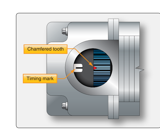
Aircraft reciprocating engines rely on magneto ignition systems to ignite the fuel-air mixture inside each cylinder at precisely the right moment. Unlike an automobile's battery-dependent ignition, a magneto is a self-contained electrical generator that produces high-voltage current without drawing anything from the aircraft's main electrical system. This independence is one of the most important safety features of any piston-powered aircraft: if the battery dies or the alternator fails entirely, the engine keeps running. Understanding how magnetos work, how they are timed to the engine, and what happens when that timing is off is essential knowledge for any Aviation Maintenance Technician (AMT) working on reciprocating powerplants.
Most certificated aircraft use a dual magneto system — two completely independent magnetos, each firing one spark plug per cylinder. This redundancy means that if one magneto fails in flight, the other continues to fire all cylinders. The slight power reduction from single-magneto operation is acceptable and detectable during the pre-takeoff runup check, where the pilot switches between LEFT, BOTH, and RIGHT positions.
How the Magneto Produces High-Voltage Spark
A magneto is essentially a specialized alternating-current generator combined with a step-up transformer. Its major internal components are the permanent magnet rotor, the primary coil, the breaker points (contact assembly), the condenser (capacitor), the secondary coil, the distributor rotor, and the distributor block.
As the engine crankshaft rotates, it also drives the magneto rotor through a gear or coupling. The spinning permanent magnet passes the pole shoes of the primary coil, creating a continuously changing magnetic flux. This changing flux induces a relatively low voltage (primary circuit voltage) in the primary coil windings. The breaker points are normally closed during this buildup, allowing primary current to flow and build a strong magnetic field around the coil.
At the precise moment the breaker points open — timed to occur just before the piston reaches the correct firing position — primary current collapses almost instantaneously. Because the secondary coil contains many more windings than the primary (the turns ratio may be on the order of 60:1 to 200:1 depending on design), the sudden collapse of the magnetic field induces an extremely high voltage surge in the secondary coil — capable of producing up to 20,000 volts or more — sufficient to jump the spark plug gap and ignite the mixture.
The condenser plays a critical but often underappreciated role: it absorbs the rush of current at the instant the points open, preventing arcing across the points. Without the condenser, the points would burn rapidly, the collapse of the magnetic field would be slowed, and secondary voltage would be insufficient to fire the plugs reliably. A faulty condenser is a common cause of magneto rough running and point erosion.
Once the high-voltage pulse exists in the secondary circuit, the distributor rotor — also driven synchronously with the engine — directs that pulse to the correct spark plug lead at exactly the right moment in the firing order. The distributor block contains individual electrodes, one per cylinder, arranged so the rotor passes each one in the engine's firing order sequence.
Ignition Timing: The Critical Relationship
Ignition timing refers to when the spark plug fires relative to piston position, expressed in degrees of crankshaft rotation before top dead center (BTDC). Fuel-air mixtures do not explode instantaneously; combustion takes a finite amount of time to propagate across the combustion chamber. To have peak combustion pressure pushing down on the piston at the optimal point in the power stroke, the spark must be initiated slightly before the piston reaches the top of its stroke.
Typical spark advance values for normally aspirated aircraft engines are commonly in the range of approximately 20° to 25° BTDC, though the exact specification varies by engine model and is always found in the manufacturer's overhaul manual or the applicable FAA-approved data. This advance allows the flame front to build pressure so that maximum force acts on the piston shortly after TDC, converting the most chemical energy into useful mechanical work.
Internal Timing vs. Engine Timing
Internal timing (also called magneto-to-magneto timing or E-gap timing) refers to the relationship between the breaker points opening and the position of the magnet rotor inside the magneto itself. Specifically, the points must open at the exact moment the rotating magnet is at the E-gap position — a precise angle past the neutral position where the rate of change of magnetic flux is greatest. At E-gap, the magnetic field is collapsing most rapidly, which produces the highest induced secondary voltage. If the points open too early or too late relative to E-gap, the output voltage drops significantly and misfires can occur, especially at high altitude or under high-power demands.
Engine timing refers to synchronizing the magneto's firing event to the correct piston position — the specified number of degrees BTDC. These two timing operations must both be correct for reliable ignition. It is entirely possible for a magneto to have correct internal timing but be installed out of time with the engine, or vice versa.
How Magneto Timing Is Set and Checked
Timing the magneto to the engine is performed using a timing light (a specialized continuity tester or LED indicator that shows when the breaker points open) in conjunction with a timing disc or protractor mounted on the crankshaft or propeller flange. The process, in general terms, is:
- Remove the top spark plugs to eliminate compression resistance and allow the crankshaft to turn freely.
- Rotate the crankshaft in the direction of normal engine rotation to the specified BTDC position for the cylinder being timed (usually cylinder No. 1 on its compression stroke).
- Connect the timing light between the magneto's primary terminal (the point at which breaker points open) and ground.
- Rotate the magneto body in its mount until the timing light indicates the breaker points just opening — that is the moment the light transitions from indicating closed to open.
- Secure the magneto at that position and verify timing with a second check.
A timing light in the closed position indicates continuity (points closed, primary circuit complete). The light changes state — indicating the circuit opens — exactly when the points separate. Precision here is critical: even a few degrees of error in timing can cause detonation, pre-ignition, loss of power, or engine damage.
Why Timing Matters for Safety and Performance
Advanced timing (spark fires too early, too many degrees BTDC) causes combustion to begin while the piston is still rising, which creates excessive cylinder pressure that fights the piston's upward travel. This can lead to detonation, pre-ignition, overheating, and structural damage to pistons, valves, and cylinder heads. Pre-ignition in particular — where the fuel-air mixture ignites before the spark even fires due to a hot spot — can destroy a cylinder in seconds.
Retarded timing (spark fires too late, too close to or after TDC) means peak combustion pressure arrives after the piston has already begun moving down the cylinder, reducing the effective work extracted from each power stroke. Symptoms include loss of power, high exhaust gas temperatures (EGT), and rough operation.
Correct timing produces smooth, complete combustion, maximum power, and appropriate cylinder head and exhaust gas temperatures — all within the limits established by the engine manufacturer.
Key Numbers and Rules
- Spark timing is specified in degrees BTDC; always consult the engine manufacturer's overhaul manual or type certificate data for exact values — never guess.
- E-gap is the position of peak flux change rate inside the magneto; points must open at E-gap for maximum secondary voltage output.
- Condenser failure leads to point arcing, erosion, and weak spark — a common source of magneto malfunction.
- The dual magneto system is required for redundancy; each magneto fires one plug per cylinder independently.
- There is no single universal mag drop limit specified by the FAA — acceptable drop on a single magneto and the maximum allowable differential between magnetos are aircraft- and engine-specific figures found in the POH/AFM; commonly cited generic guidance is roughly 125-150 RPM maximum drop with no more than about 50 RPM difference between the two magnetos, but the applicable aircraft's published limits always govern.
- The ignition switch grounding wire (P-lead) connects the primary circuit to ground when the magneto is switched OFF; a broken P-lead means the magneto remains HOT even with the switch off — an extremely dangerous condition during engine shutdown and preflight.
- Timing checks must be performed in the direction of normal engine rotation to eliminate gear backlash error.
Common Test Traps
- Confusing internal timing with engine timing: The FAA written test often presents scenarios where one is correct and the other is not. Remember that internal (E-gap) timing and engine-to-magneto timing are separate procedures that must both be verified.
- The P-lead misconception: Many students assume that turning the ignition switch OFF de-energizes the magneto electrically. In fact, the magneto is always capable of generating spark as long as it is spinning — the P-lead simply grounds the primary circuit to suppress output. A broken P-lead is a live magneto.
- Effect of timing on EGT vs. CHT: Retarded timing causes high EGT; advanced timing tends to raise CHT and can cause detonation. Test questions may ask which direction of timing error produces which symptom.
- Condenser vs. points diagnosis: A magneto that runs rough at high power or high altitude but seems fine at idle often has a failing condenser or worn points — not necessarily a distributor or coil problem.
- Firing order vs. distributor sequence: The distributor rotor must align with the correct cylinder electrode in the correct firing order. Installing a distributor incorrectly (180° out, for example) can cause the magneto to fire on the exhaust stroke rather than the compression stroke — the engine may start but will run very rough and at reduced power.