When a pilot enters the clouds and loses all visual reference to the horizon, the cockpit instruments become the only reliable source of aircraft orientation. Three of the most critical flight instruments—the attitude indicator, the heading indicator, and the turn coordinator—are built around spinning gyroscopes. Understanding why a gyroscope works the way it does is not just an abstract physics exercise; it directly explains why these instruments behave as they do, what their limitations are, and how to catch them when they lie. The FAA knowledge test probes this topic regularly, and instrument pilots who truly grasp gyroscopic principles make far fewer errors when cross-checking their instrument scan.
A gyroscope, in the aviation context, is simply a wheel or rotor that spins at high speed around an axis. That spinning mass produces two remarkable properties: rigidity in space and precession. Every gyroscopic instrument in the aircraft uses one or both of these properties to do its job.
Rigidity in Space
Rigidity in space (sometimes called gyroscopic inertia) is the tendency of a spinning gyroscope to resist any change in the orientation of its spin axis. The faster the rotor spins and the greater its mass, the stronger this rigidity. Newton's first law of motion underlies this behavior: a rotating mass, like any mass in motion, resists changes to its state of motion.
From a practical standpoint, rigidity means that a gyroscope's spin axis will continue pointing in the same direction relative to inertial space (the stars, not the Earth) regardless of how the frame supporting it is tilted, turned, or pitched. This is exactly the property exploited by the attitude indicator and the heading indicator. Mount a gyroscope in a gimbal system that allows the aircraft to rotate freely around it, and that gyroscope's stable axis gives you an unwavering spatial reference—an artificial horizon or a directional benchmark—even when the aircraft is pitched, rolled, or yawing through clouds.
The attitude indicator's gyro rotor is oriented with its spin axis vertical. As the aircraft pitches and rolls, the gyro stays level with the Earth's surface (because it is rigid in space), while the instrument case and the miniature airplane symbol move around it. The pilot reads pitch and bank from the relative movement between the case and the gyro-stabilized horizon bar. The heading indicator's gyro spin axis is horizontal, oriented to remain pointed in a fixed compass direction once set, giving the pilot a vibration-free directional reference that the magnetic compass cannot provide during turns and acceleration.
Precession
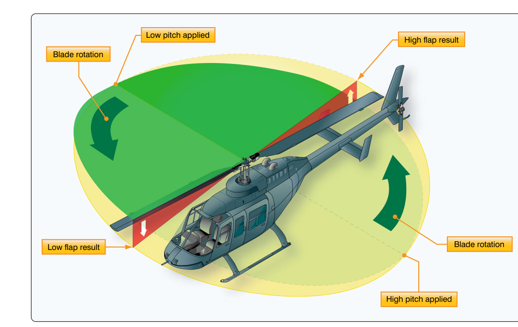
Precession is the second key gyroscopic property, and it is the one that surprises most students. When an external force is applied to a spinning gyroscope, the gyro does not respond immediately in the direction of that force. Instead, the gyro responds 90 degrees later in the direction of rotation. In other words, the effective reaction occurs at a point 90 degrees around the rotor from where the force was applied, in the direction the rotor is turning.
A common classroom demonstration: hold a spinning bicycle wheel by the axle. Try to tilt the axle downward. Instead of tilting downward, the axle swings sideways. That perpendicular reaction is precession. For aircraft instruments, precession is both a functional tool and a source of error.
The turn coordinator (and its predecessor, the turn-and-slip indicator) uses precession to sense rotation. When the aircraft yaws or rolls into a turn, that rotational force is applied to the gyro rotor. The gyro precesses in response, and that precession deflects the instrument needle or rotates the miniature aircraft symbol, indicating the rate of turn. The faster the aircraft turns, the greater the applied force, and the greater the precession and instrument deflection. At standard rate (3 degrees per second), the miniature wings of a turn coordinator align with the index marks.
It is important to understand that the turn coordinator senses both roll and yaw because its gyro axis is canted roughly 30 degrees from horizontal, while the older turn-and-bank indicator's gyro senses yaw only (its axis is horizontal). This is why the turn coordinator gives an earlier indication of entry into a turn—it reacts to the initial roll—while the turn-and-bank indicator waits for the yaw to develop.
Gyroscopic Power Sources
Gyro rotors must spin at very high speeds—typically thousands of RPM—to develop useful rigidity. Aircraft gyros are powered by one of two sources: vacuum (suction) systems or electrical systems. Most light aircraft use a vacuum pump driven by the engine to spin the attitude indicator and heading indicator through air jets directed at buckets cut into the rotor rim. The turn coordinator is typically electrically driven, providing a backup if the vacuum system fails.
Vacuum system pressure is critically important. Most systems are designed to operate at approximately 4.5 to 5.5 inches of mercury (check the specific aircraft's POH). If suction is too low—due to a failing pump, blocked filter, or regulator issue—the gyros will under-spin, reduce their rigidity, and give slow or erratic indications. A pilot flying IMC with a degraded vacuum system may not notice the subtle drift of the attitude indicator until the aircraft is significantly off the intended attitude. This is why checking the suction gauge is part of every IFR scan.
Gyroscopic Errors and Precession-Induced Drift
Because rigidity keeps the gyro pointing at a fixed point in inertial space, and because the Earth is rotating beneath it, the gyro gradually appears to drift relative to the Earth. This is called apparent precession or apparent drift. The heading indicator is particularly affected—on average it can drift several degrees every 15 minutes—which is why pilots must re-synchronize it to the magnetic compass approximately every 15 minutes during flight, or more frequently near the poles where Earth's rotation effect is amplified.
A second type of drift, real precession, occurs due to mechanical imperfections: bearing friction, imbalance, and gimbal bearing friction all apply small, continuous torques to the gyro, causing its axis to slowly wander from its intended orientation. High-quality instruments minimize but cannot eliminate this effect.
The attitude indicator is also subject to a phenomenon called gimbal error (or gimbal lock in extreme cases), which occurs in steep bank attitudes beyond the instrument's designed range—typically beyond 60–70 degrees of bank or 85 degrees of pitch. During aerobatic or unusual attitude recovery, pilots should be aware that some attitude indicators may tumble and give false indications until they erect themselves, which takes time.
Why It Matters for IFR Flight
A solid understanding of gyroscopic principles directly supports safer instrument flying. Knowing that the heading indicator drifts reminds you to cross-check and reset it regularly. Knowing that a vacuum failure will degrade your two primary gyro instruments (attitude and heading indicators) underscores the importance of monitoring the suction gauge and being ready to transition immediately to partial-panel flight—using the magnetic compass and turn coordinator. Knowing that the turn coordinator is electrically driven and will survive a vacuum failure tells you which instruments remain trustworthy.
Precession also explains why, when a gyro instrument's gimbal locks up, a sudden erroneous reading can appear. The energy of a constraint applied to the rotor transfers 90 degrees—the gyro's reaction appears where the force is not expected—and the instrument needle swings in a direction that feels counterintuitive. Recognizing this behavior allows you to flag an instrument as suspect and rely on others.
Key Numbers and Rules
- Standard-rate turn: 3 degrees per second; a full 360-degree turn takes exactly 2 minutes.
- Typical vacuum system operating range: approximately 4.5–5.5 inches of mercury (verify in the aircraft's POH).
- Heading indicator drift: up to several degrees per 15 minutes; re-synchronize to magnetic compass every 15 minutes in flight.
- Attitude indicator limits: typically ±60–70 degrees of bank and ±85 degrees of pitch before the gyro may tumble.
- Precession response: force applied at one point → reaction appears 90 degrees later in the direction of rotor spin.
- Turn coordinator gyro axis: canted ~30 degrees from horizontal, sensing both roll and yaw.
- Turn-and-bank indicator gyro axis: horizontal, sensing yaw only.
Memory Aid
"RAP" — Rigidity, Axis, Precession (90 degrees)"
- R — Rigidity: The spinning gyro resists changes to its spin axis orientation.
- A — Axis (stays fixed in inertial space): The gyro axis points at the same spot in space regardless of how the airframe moves around it.
- P — Precession (90 degrees in the direction of spin): Any force applied to the gyro produces a reaction 90 degrees later in the direction of rotation, not at the point of application.
Common Test Traps
- Precession direction confusion: Many students think a force applied to the top of a gyro causes it to tilt toward the force. It does not—the response occurs 90 degrees around the rotor in the direction of spin. Always trace the direction of rotation to find where the reaction appears.
- Vacuum vs. electrical instrument mix-up: The FAA frequently tests which instruments are vacuum-driven and which are electric. Remember: attitude indicator and heading indicator are typically vacuum-driven; the turn coordinator is typically electric. A vacuum failure leaves the turn coordinator intact.
- Heading indicator drift ignored: Expecting the heading indicator to be self-correcting like a magnetic compass is wrong. It drifts due to apparent and real precession. The magnetic compass is the corrective reference, not the other way around.
- Turn coordinator vs. turn-and-bank: The test often asks which instrument senses roll as well as yaw. The turn coordinator (canted gyro axis) senses both; the older turn-and-bank indicator senses yaw only.
- Low suction = false attitude indications: Students sometimes assume a gyro instrument either works perfectly or fails completely. In reality, under-spinning gyros give sluggish, drifting, or progressively erroneous indications—a subtle and dangerous failure mode.