Three of the most important flight instruments in a light aircraft — the attitude indicator, the heading indicator, and the turn coordinator — all depend on the physics of spinning gyroscopes. Yet many student pilots treat these instruments as magic boxes, reading the numbers without understanding why they work or why they sometimes err. A solid grasp of gyroscopic principles transforms an abstract instrument scan into genuine situational awareness and helps you anticipate instrument behavior, recognize failures, and pass the FAA knowledge test with confidence.
A gyroscope, at its simplest, is a mass that spins rapidly around an axis. When that mass spins fast enough, it exhibits two remarkable properties: rigidity in space and precession. Everything about gyroscopic flight instruments flows from these two principles.
Rigidity in Space
Rigidity in space — sometimes called gyroscopic inertia — is the tendency of a spinning gyroscope to resist any force that tries to change the orientation of its spin axis. Once a gyro is spinning, it wants to keep pointing in the same direction relative to the stars (inertial space), regardless of how the platform around it tilts, turns, or moves.
Think about a toy top spinning on a table. If you try to push its axis sideways, it pushes back. The faster it spins and the greater its mass, the more stubbornly it resists. Aircraft gyros use the same physics. An electric attitude indicator spins its gyro wheel at roughly 10,000–18,000 RPM, and a vacuum-driven gyro typically operates between 10,000–15,000 RPM. At those speeds, the wheel has enormous rigidity. When the aircraft pitches nose-up, the gyro wheel stays pointed at the horizon while the aircraft frame — and the instrument face — rotates around it, giving the pilot a clear picture of bank and pitch attitude.
This property makes the attitude indicator (AI) and the heading indicator (HI, also called the directional gyro or DG) possible. The AI uses a gyro mounted so its spin axis is vertical, allowing it to sense both pitch and bank. The HI uses a gyro with a horizontal spin axis to maintain a fixed compass heading reference that does not wander with magnetic fluctuations or acceleration errors the way a magnetic compass does.
Precession
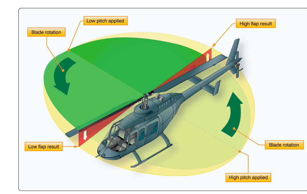
Precession is the second defining behavior of a gyroscope, and it is counterintuitive enough that it catches many students off guard. When you apply a force to the rim of a spinning gyroscope, the gyro does not respond in the direction of the applied force. Instead, it responds 90° ahead in the direction of rotation. In other words, the effect appears a quarter-turn later around the spin axis from where the force was applied.
A classic way to visualize this: imagine a gyro wheel spinning counterclockwise when viewed from the front. If you press down on the top of the wheel, the gyro does not tilt backward (away from you). Instead, it tilts to the left — 90° around in the direction of spin from the point where you pushed. That displacement is precession.
The magnitude of the precession rate depends on two factors: the strength of the applied force and the angular momentum of the gyro (which is determined by its mass, radius, and spin speed). A stronger force or a slower, lighter gyro produces more precession; a heavier, faster gyro with the same applied force precesses less, demonstrating better rigidity.
How These Principles Power Each Instrument
Attitude Indicator
The AI relies almost entirely on rigidity in space. Its gyro is erected to vertical (either by vacuum-driven air jets or electrically) during normal operation. As the airplane pitches and rolls, the gyro remains spatially fixed while the miniature airplane on the instrument face moves relative to the artificial horizon bar, telling the pilot the aircraft's actual attitude. Precession matters here mainly as an error source: any unbalanced forces on the gyro (such as those from prolonged unusual attitudes) can slowly precess the gyro away from true vertical, causing slight attitude errors after extended aerobatic maneuvering or during unusual attitude recovery training.
Heading Indicator
The HI also depends on rigidity to maintain a fixed directional reference. However, precession is the reason the HI must be realigned to the magnetic compass every 15 minutes or so during flight. Bearing friction, imperfect gyro balance, and — importantly — the rotation of the Earth itself all apply small, continuous torques to the gyro. Through precession, these tiny forces gradually cause the HI to drift away from its set heading. At mid-latitudes in the continental United States, apparent drift from Earth rotation alone can be several degrees per hour; mechanical drift from bearing friction adds more. The total is often 3°–5° per 15 minutes, so the FAA and manufacturers recommend periodic re-synchronization.
Turn Coordinator and Turn-and-Slip Indicator
The turn coordinator (and its older sibling, the turn-and-slip indicator) uses precession deliberately to measure the rate of turn. The gyro in a turn coordinator is canted approximately 30° from horizontal so it can sense both roll rate and yaw rate. When the aircraft yaws in a turn, a force is applied to the gyro, and through precession, the gyro tilts in response. This tilt moves the miniature aircraft (or needle) on the face of the instrument, indicating the rate of turn. A standard-rate turn is 3° per second, and the turn coordinator is calibrated so that when the miniature aircraft's wingtip aligns with the index mark, the aircraft is turning at exactly that rate — completing a full 360° turn in two minutes.
The ball (inclinometer) in the lower part of both the turn coordinator and the turn-and-slip indicator is not gyroscopic at all. It is a simple curved glass tube filled with liquid and a ball bearing, responding to the balance of gravity and centrifugal force to show whether the aircraft is in coordinated flight, a slip, or a skid.
Why This Matters: Real-World and Safety Implications
Understanding gyroscopic principles directly affects flight safety. A vacuum-system failure will cause both the attitude indicator and heading indicator to slowly tumble and give false readings, often within minutes. Because of rigidity, the gyros spin down gradually — they don't fail instantly — which means an unwary pilot can receive convincingly wrong attitude information for several minutes before the instruments fully tumble. Knowing that the AI and HI share the same vacuum source (in most single-engine trainers) means that if one fails, the other is suspect too. Cross-checking with the magnetic compass and the turn coordinator (which is typically electrically powered) is the proper response.
Precession also explains a phenomenon called gyroscopic effect or gyroscopic precession of the propeller, which is a flight characteristic — not an instrument issue — tested on the FAA knowledge exam. The propeller of a single-engine aircraft is itself a large gyroscope. When the pilot pushes the nose down (applies a downward force at the top of the prop arc), precession causes the nose to yaw to the left (for a clockwise-rotating propeller as viewed from the cockpit). This is one of the four left-turning tendencies of single-engine propeller aircraft and is most noticeable during abrupt pitch changes, particularly in tailwheel aircraft during the takeoff roll.
Key Numbers and Rules
- Gyro spin speed: Vacuum-driven gyros typically spin at 10,000–15,000 RPM; electric gyros may reach 18,000 RPM or more.
- Standard-rate turn: 3° per second, completing 360° in 2 minutes — the turn coordinator index mark represents this rate.
- HI realignment interval: Every 15 minutes in cruise flight, or more often if significant drift is noted.
- Precession direction rule: Effect appears 90° ahead in the direction of gyro rotation from the point of applied force.
- Vacuum system pressure: Most gyros require approximately 4.5–5.4 inches of mercury (in. Hg) of suction to operate correctly; a suction gauge should be checked during preflight and periodically in flight.
- Instruments sharing vacuum: In most GA aircraft, the AI and HI are vacuum-powered; the turn coordinator is typically electric — giving the pilot at least one gyroscopic reference during a vacuum failure.
Memory Aid
"RAP" — Rigidity, Applied force, Precession. Use it to reconstruct the cause-and-effect chain: the gyro's Rigidity keeps the spin axis fixed; when an external Applied force acts on the spinning gyro, the result is Precession — a response 90° ahead in the direction of rotation. Walk through RAP any time an exam question describes a gyro behavior, and you can reason out the correct answer even if you have not memorized that specific scenario.
Common Test Traps
- Confusing which instruments are vacuum vs. electric: The FAA commonly asks which instrument remains usable after a vacuum failure. Remember: the turn coordinator is typically electric; the AI and HI are typically vacuum.
- Misidentifying the direction of precession: The effect is 90° ahead in the direction of rotation, not simply 90° to the right or left in the aircraft's frame. Always identify the spin direction first.
- Assuming the HI is always accurate: The HI has no magnetic sensing ability — it drifts with time and must be set using the magnetic compass. Questions about the HI reading after a long flight without re-sync are testing this limitation.
- Confusing the ball with a gyroscopic instrument: The inclinometer ball in the turn coordinator is purely gravity/centrifugal — it has no gyro. It is not affected by vacuum or electrical failure.
- Forgetting propeller gyroscopic precession as a left-turning tendency: The exam may describe an abrupt pitch change in a propeller aircraft and ask what yaw results. Apply the 90° rule to the propeller disk to find the correct answer.