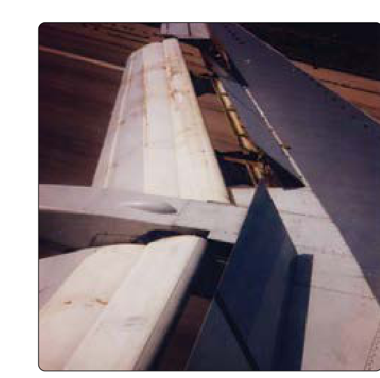
Transport-category aircraft operate in a regime where kinetic and potential energy accumulate rapidly. A modern widebody cruising at Mach 0.85 and flight level 390 carries an enormous energy state that neither the elevator nor throttle can manage alone during a steep descent or a short-runway landing. Spoilers and speed brakes—flat panels hinged into the upper wing surface—are the primary tools used to address this challenge. They simultaneously reduce lift and multiply drag, and their hydraulic actuation systems are engineered with redundancy specifically because control authority and stopping performance depend on them. For the ATP candidate, a surface-level understanding of these devices is not enough; the aerodynamic physics, hydraulic architecture, system limitations, and operational consequences must all be thoroughly internalized.
What Spoilers and Speed Brakes Are
The terms spoiler and speed brake are often used interchangeably in casual conversation, but they describe overlapping—not identical—functions. A spoiler is any hinged upper-surface panel that, when raised, physically interrupts the smooth boundary layer airflow over the wing, reducing the pressure differential between upper and lower surfaces. This directly reduces lift and increases pressure drag. A speed brake is a device used symmetrically to increase drag without inducing roll. On most transport aircraft, the same physical panels serve both roles depending on how they are commanded.
A typical transport aircraft wing carries a bank of five to eight spoiler panels per side, arranged spanwise between the inboard and outboard sections of the wing. These are subdivided by function:
- Ground spoilers (sometimes called lift-dump spoilers): all or most panels deploy fully—often to 60 degrees or more—but only on the ground. They are either manually selected or automatically armed to deploy when weight-on-wheels sensors confirm touchdown.
- Flight spoilers: a subset of panels that can deploy in the air. They operate both symmetrically (as speed brakes) and asymmetrically (as roll spoilers to augment aileron authority).
- Roll spoilers: flight spoiler panels driven by the lateral control system. On the wing going down, spoiler panels rise to reduce lift and increase drag on that side, banking the aircraft. On most designs, the opposite wing's spoilers remain retracted.
Aerodynamic Effects in Detail
Lift Reduction and Drag Increase
When a spoiler panel rises, it separates the boundary layer from the upper wing surface downstream of the hinge. This separated, turbulent airflow produces two simultaneous effects: the wing generates less lift because the pressure differential is disrupted, and pressure drag rises sharply because the separated wake has much higher energy loss than attached flow. The net result is a steep increase in the lift-to-drag ratio's denominator with a simultaneous decrease in the numerator—precisely the opposite of what a wing is designed to do. Pilots experience this as a rapid increase in sink rate and deceleration during flight spoiler deployment, or as an immediate weight transfer to the gear on landing.
Pitching Moment
A commonly misunderstood effect is the pitching moment produced by symmetrical spoiler deployment. Pilots often expect a nose-up tendency by analogy to increased drag or flap extension, but the pitch response to spoiler deployment is airplane-specific and must be verified against the AFM rather than assumed from a single universal rule. On many transport aircraft, symmetric spoiler deployment produces a mild nose-down pitch tendency, often attributed to reduced wing downwash reaching the horizontal tail (less downwash can increase tail lift, pitching the nose down), while other designs exhibit a mild nose-up tendency or minimal pitch change depending on spoiler location and tail configuration. Because the response varies by type, the correct technique is to apply whatever control input is needed—as trained in that aircraft's AFM procedures—to maintain the desired pitch attitude when flight spoilers are extended. During steep, high-energy descents where flight spoilers are held fully extended, pilots must actively manage pitch attitude throughout the maneuver.
Stall Speed Increase
Spoilers reduce the wing's maximum lift coefficient (CL max). Because stall occurs at CL max, any reduction in that value means the wing reaches its maximum lift at a higher airspeed—in other words, stall speed increases. With flight spoilers extended, the aircraft will stall at a higher indicated airspeed than with a clean wing, and substantially higher than with full flaps deployed. The practical implication is that speed brakes should not be used on approach in a manner that eats into the required stall margin without accounting for the elevated stall speed in VREF additive calculations as specified in the Aircraft Flight Manual (AFM). Some AFMs prohibit flight spoiler use below certain altitudes or flap configurations on approach for exactly this reason.
Buffet, Structural Loads, and Speed Limits
Raising spoiler panels at high airspeeds introduces significant aerodynamic loads onto the panels themselves and into the wing structure at the hinge attachments. Each aircraft's AFM publishes a maximum speed for speed brake extension, and deployment above this speed risks structural damage and severe airframe buffet. This speed is always less than VMO/MMO and must be respected as a hard limit. Additionally, turbulence penetration speeds and speed brake placard speeds interact: in moderate to severe turbulence, the combination of gust loads and spoiler-induced structural loads could approach design limit load—another reason the AFM's guidance is authoritative.
Hydraulic Actuation and System Redundancy
On transport-category aircraft, spoiler panels are hydraulically actuated. Each panel is driven by a hydraulic actuator powered from one of the aircraft's multiple independent hydraulic systems. The panels are deliberately distributed across hydraulic systems so that the loss of any single hydraulic system does not result in total loss of spoiler function. For example, on a typical twin-hydraulic aircraft, inboard flight spoilers may be powered by System A and outboard flight spoilers by System B. Ground spoilers may draw from both systems or include a dedicated circuit.
The practical consequence of hydraulic system failure for the ATP candidate is nuanced:
- A single hydraulic failure reduces the number of available spoiler panels, which reduces maximum drag capability. Descent profiles may need to be extended, and landing distance may increase.
- Roll spoiler authority is degraded because only panels on one hydraulic circuit are available on each wing. The flight control computer (or the pilot in non-fly-by-wire designs) must account for reduced roll augmentation, particularly at high speeds where ailerons alone may be insufficient.
- Some older designs require manual speed brake operation if auto-speed brake systems lose hydraulic pressure, requiring the pilot to manually arm and verify deployment at landing.
The PHAK and systems-specific training materials emphasize that hydraulic failure checklists always include an assessment of spoiler and flight control authority. This is not merely a systems consideration—it directly affects both controllability and landing performance planning under 14 CFR Part 25 certification standards for transport-category aircraft.
Ground Spoilers and Lift Dump
The concept of lift dump is central to understanding why ground spoilers are not optional. At touchdown, with all spoiler panels fully deployed, the wing's remaining lift is almost entirely eliminated. The full weight of the aircraft is transferred to the main gear. Because wheel brake effectiveness (friction force) is a function of the normal force between tire and runway—which is proportional to the weight on the wheels—maximum braking force is only available when aerodynamic lift is fully dumped. An aircraft landing with lift remaining under the wings can generate considerably less braking friction even with maximum brake pedal input. Combined with thrust reversers, which are also more effective once the aircraft is fully on the ground, lift dump is the foundational step in achieving minimum landing distance. Auto-spoiler systems that deploy upon weight-on-wheels contact or upon thrust reverser deployment are designed to eliminate any delay in this critical first step of the stopping sequence.
Key Numbers, Rules, and Limitations
- Maximum speed for speed brake extension: always published in the AFM; typically below VMO; must not be exceeded.
- Ground spoiler deployment angle: commonly 45–60 degrees or greater for maximum lift dump effectiveness.
- Stall speed increases with flight spoilers extended; VREF additives must reflect this if spoilers are used on approach.
- Pitch change from symmetric spoiler deployment is airplane-specific—many transport types show a mild nose-down tendency, but the direction and magnitude must be verified against the AFM rather than assumed.
- Hydraulic redundancy: spoiler panels are distributed across multiple hydraulic systems per 14 CFR Part 25 requirements to ensure continued controllability after a single system failure.
- Asymmetric spoiler deployment for roll control is especially important at high speeds to supplement ailerons and prevent aileron reversal on flexible wings.
Common Test Traps
- Ground spoilers vs. flight spoilers: Ground spoilers deploy only on the ground (or are armed for automatic deployment at touchdown). Flight spoilers can deploy in the air. Confusing which panels are available in-flight is a frequent error on the ATP Airplane written test.
- Pitch direction: Candidates who assume a single universal pitch response are caught off guard. Symmetric spoiler deployment often produces a mild nose-down pitching moment on transport types, but the response varies by airplane design and must be confirmed against the AFM rather than assumed from a generic rule.
- Stall speed and approach planning: Partial speed brake extension during approach raises stall speed and must be factored into approach speed—it does not create the same margin as a clean configuration at the same speed.
- Hydraulic failure and performance: A question describing a hydraulic system failure is not purely a systems question. It has a direct answer in terms of reduced spoiler panels, degraded roll authority, and potentially increased landing distance that must be planned for.
- Auto-spoiler arm: Forgetting to arm auto-spoilers before landing is a checklist trap. If not armed, ground spoilers will not deploy automatically at touchdown, significantly increasing landing distance.