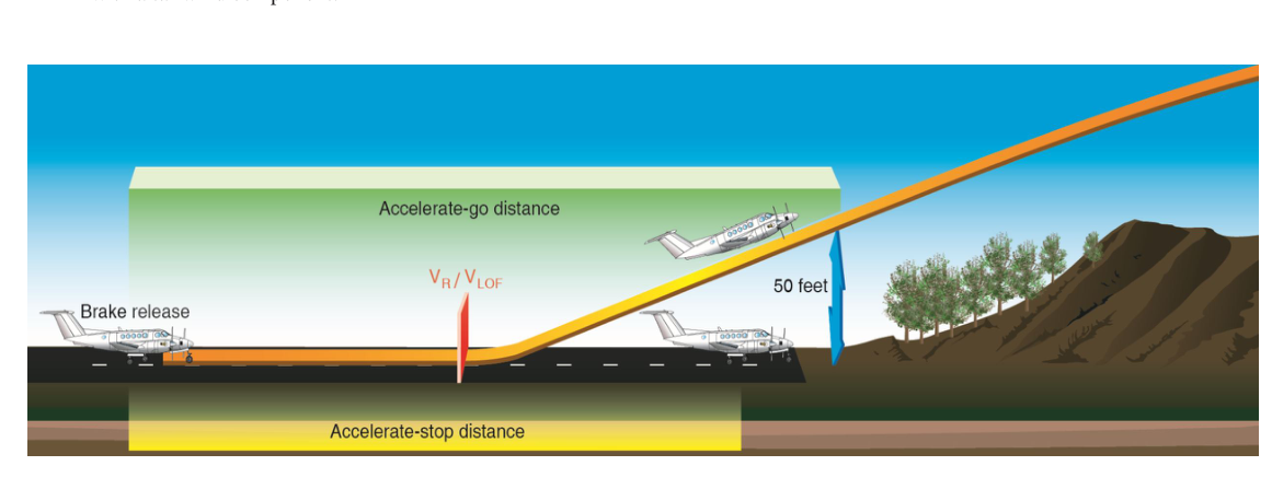
Every transport-category departure begins with a fundamental question: if an engine fails at the worst possible moment, can the crew either stop safely before the pavement ends or fly away safely over a 35-foot obstacle? These two obligations — the accelerate-stop requirement and the accelerate-go requirement — are simultaneously imposed by 14 CFR Part 25 and Part 121, and the speed at which they intersect is called the balanced field V1. Understanding how these distances are defined, calculated, corrected, and compared is one of the most heavily tested subjects on the ATP Airplane and Aircraft Dispatcher knowledge tests.
Defining the Key Distances
Before any calculation can begin, the crew and dispatcher must know what distances are actually available on a given runway. The FAA defines four declared distances for each runway, published in the Airport/Facility Directory (now the Chart Supplement) and in NOTAM form when changed:
- TORA (Takeoff Run Available): The length of runway declared available for the ground roll portion of a takeoff. This is typically equal to the physical runway length.
- TODA (Takeoff Distance Available): The TORA plus any declared clearway. A clearway is a defined rectangular area beyond the runway, free of obstructions, that can be credited toward the airborne portion of the takeoff distance — but only for the portion of flight after liftoff, and only up to one-half the airborne distance from liftoff to the 35-foot screen height.
- ASDA (Accelerate-Stop Distance Available): The TORA plus any declared stopway. A stopway is a prepared area beyond the runway capable of supporting the aircraft during an aborted takeoff. Unlike a clearway, it bears the aircraft's weight and can be credited toward stopping distance.
- LDA (Landing Distance Available): The runway length available for landing — often shorter than TORA if a displaced threshold exists.
The critical regulatory relationship is simply stated: ASDA must be greater than or equal to the Accelerate-Stop Distance Required (ASDR), and TODA must be greater than or equal to the Takeoff Distance Required (TODR), for the planned takeoff weight, environment, and V1 selection.
Accelerate-Stop Distance: What It Really Measures
The Accelerate-Stop Distance Required (ASDR) is the total ground distance needed to perform the following certified sequence: accelerate on all engines to V1, experience a critical engine failure exactly at V1, recognize the failure, decide to abort, retard thrust levers to idle, apply maximum braking and ground spoilers (and, where the aircraft performance data accounts for it, thrust reversers), and decelerate to a complete stop. Every phase — the all-engine acceleration roll, the brief one-second recognition and reaction time built into the certification standard, and the deceleration roll — consumes runway.
It is worth emphasizing what V1 actually means. Per 14 CFR Part 25, V1 is the takeoff decision speed: the speed above which the pilot must not initiate the first action to abort the takeoff, and below which the pilot must be capable of stopping within the available field. By the time the aircraft reaches V1, the pilot must already be committed. The recognition delay is accounted for inside the certification data — crews should not be making the stop-or-go decision at V1; the decision process should be complete at V1.
Accelerate-Go Distance and the 35-Foot Screen
The complementary distance is the Takeoff Distance Required (TODR) for a continued (engine-out) takeoff. This begins at brake release, includes the all-engine acceleration phase to V1, the engine failure at V1, continued acceleration on the remaining engine(s) to VR (rotation speed), rotation to liftoff at VLOF, and climb to clear a 35-foot obstacle at the end of the takeoff distance. The 35-foot screen applies to the net flight path, not the gross path — a safety margin is built in by subtracting a climb gradient increment from the actual aircraft capability.
Notice that V1 appears in both calculations. This is the heart of balanced field analysis:
- If V1 is increased, the aircraft accelerates further before the abort decision, consuming more runway before braking begins — ASDR increases. At the same time, the aircraft is moving faster when the engine fails, so less additional runway is needed to reach VR and 35 feet — TODR decreases.
- If V1 is decreased, the aircraft stops in less distance — ASDR decreases — but needs more distance to climb out on the remaining engine — TODR increases.
The Balanced Field Concept
The balanced field V1 is the specific V1 at which ASDR equals TODR. At this speed and the corresponding balanced field length, the airplane is equally capable of stopping or continuing, and the total field length required is minimized. Selecting any other V1 value causes one of the two required distances to grow longer than necessary, effectively requiring a longer runway.
The balanced field length is therefore the minimum runway (plus applicable clearway/stopway credit) that satisfies both Part 25 requirements simultaneously. Real airline performance software iterates through V1 values to find this intersection, then checks the result against TODA, ASDA, and the obstacle-clearance net flight path — all three must be independently satisfied.
Environmental Correction Factors
AFM takeoff performance data is certified at specific reference conditions; every real-world departure requires corrections. Understanding how each factor moves the numbers is critical for exam questions:
- Pressure altitude and temperature: Higher density altitude reduces engine thrust and aerodynamic lift, lengthening both ASDR and TODR significantly. Hot-and-high airports dramatically shrink allowable takeoff weights.
- Wind: A headwind reduces groundspeed at any given airspeed, shortening both the acceleration roll and the stop roll. A tailwind does the opposite — it is the single most operationally significant correction for many performance-limited departures. Part 25 certification allows only 50% headwind credit and requires 150% tailwind penalty to account for variability.
- Runway slope: An uphill slope adds a deceleration force that aids stopping (shorter ASDR) but resists acceleration (longer TODR). A downhill slope does the reverse.
- Runway surface condition: A wet runway substantially reduces the braking friction coefficient, greatly increasing ASDR. Part 25 Amendment 92 and later amendments require operators to use a separate wet runway accelerate-stop distance, which can be thousands of feet longer than the dry value. Contaminated runways (snow, slush, ice) require additional analysis beyond the standard wet charts.
- Aircraft weight: Heavier aircraft require more distance to accelerate and to stop. Maximum allowable takeoff weight for a given runway is often determined by the balanced field analysis rather than structural limits.
Regulatory Requirements: Part 121 Operations
Under 14 CFR Part 121, an air carrier must show before each departure that the planned takeoff weight does not exceed the maximum weight allowing the airplane to: (1) accelerate and stop within ASDA on a dry runway using the AFM dry data (or the wet data if the runway is wet or contaminated); (2) accelerate and continue to climb to 35 feet within TODA; and (3) clear all obstacles in the departure path by the required net obstacle-clearance margin. The most restrictive of the climb-limited, field-length-limited, obstacle-limited, and brake-energy-limited weights becomes the regulated takeoff weight for that operation. Dispatchers compute this weight and the corresponding V1, VR, and V2 speeds, which are then provided to the crew on the takeoff data card or electronic flight bag.
Key Numbers and Rules to Remember
- The 35-foot obstacle screen height is used for takeoff distance (Part 25 dry runway standard).
- Clearway credit is limited to a maximum of one-half the airborne distance from liftoff to the 35-foot height.
- Stopway may be credited toward ASDA but not toward airborne distance.
- Part 25 headwind credit: 50% of reported headwind; tailwind penalty: 150% of reported tailwind component.
- V1 must be at or above VMCG (minimum control speed, ground) and at or below VR.
- Brake-energy limits may set a maximum V1 independently of the balanced field analysis.
Common Exam Traps
- Clearway vs. stopway confusion: Clearways extend TODA for airborne distance credit only. Stopways extend ASDA for stopping credit only. They are not interchangeable, and this distinction appears repeatedly on knowledge tests.
- V1 is a decision speed, not a rotation speed: VR always occurs after V1 in a continued takeoff. Candidates sometimes reverse the order.
- Using dry charts on a wet runway: The wet ASDR is always greater than the dry value. Using dry data on a wet runway is both a regulatory violation and a safety hazard.
- Balanced does not mean shortest individual distance: It means the field length that satisfies both requirements with the lowest total pavement demand. An unbalanced V1 can require more total runway even if it shortens one of the two individual distances.
- One-engine-inoperative climb gradient requirements are separate from field length — an aircraft may be field-length limited to a weight that still violates climb gradient requirements. Both must be independently checked.
Memory aid
Picture V1 as the fulcrum of a see-saw: the left side is ASDR (stop distance) and the right side is TODR (go distance). Sliding the fulcrum right (raising V1) tips the left side up and lowers the right — stop gets harder, go gets easier. Sliding it left (lowering V1) does the reverse. Balance the see-saw and you minimize the total board length you need.