Swept wings define virtually every modern jet transport, and the aerodynamic trade-off they represent sits at the heart of transport-category handling characteristics. The ATP Airman Certification Standards require candidates to understand not just what sweepback does, but why it creates predictable low-speed hazards and how manufacturers and pilots manage them. This article works through the full cause-and-effect chain — from high-speed compressibility relief to low-speed tip stall and pitch-up instability — with the depth that demanding written tests and oral exams require.
Why Wings Are Swept: Compressibility and the Critical Mach Number
As an aircraft accelerates toward its critical Mach number (Mcrit), airflow accelerating over the upper wing surface reaches Mach 1.0 locally before the aircraft itself does. Shockwave formation at that point causes a dramatic rise in wave drag and changes in pitching moment that designers must either avoid or manage. Sweepback is the primary tool for pushing Mcrit to a higher indicated Mach number.
The physical principle is straightforward: only the component of the freestream velocity that is perpendicular to the leading edge contributes to lift and compressibility effects. On a wing swept back 35 degrees, that perpendicular component is reduced by the cosine of 35 degrees — roughly 82 percent of actual flight speed. The wing effectively operates in a lower effective Mach environment than the aircraft's true speed, allowing efficient cruise well into the high-subsonic regime. Modern transports routinely cruise between Mach 0.78 and Mach 0.86 precisely because their swept planforms delay the drag-rise associated with shock formation. Without sweep, those cruise speeds would be impossible at acceptable fuel burn.
The Spanwise Flow Problem
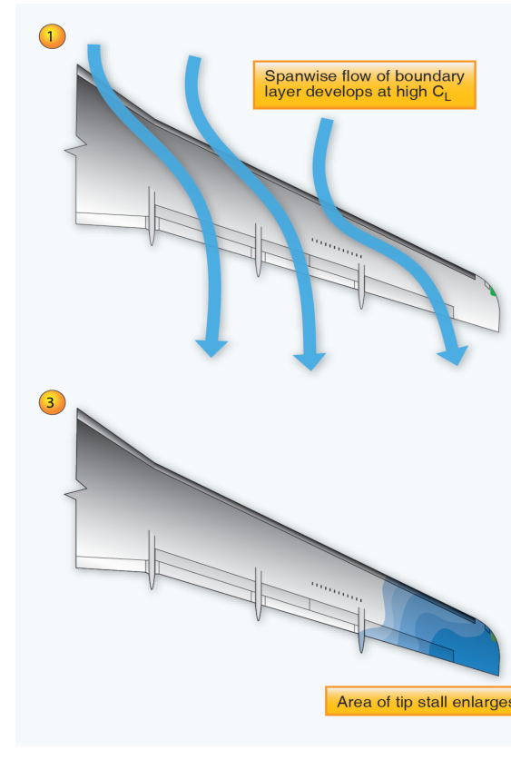
The same geometric feature that buys high-speed efficiency creates a fundamental low-speed liability: spanwise boundary-layer migration. On any wing, a pressure gradient exists between the high-pressure lower surface and the low-pressure upper surface. On a straight wing, this gradient drives airflow predominantly chordwise — straight back toward the trailing edge. On a swept wing, however, the pressure gradient has a significant component directed outward toward the wingtip, and the slow, low-energy air in the boundary layer follows that gradient diagonally.
As boundary-layer air accumulates spanwise, the boundary layer thickens progressively toward the tip. A thick, low-energy boundary layer is far more susceptible to adverse pressure gradients and flow separation than the thin, energetic boundary layer near the root. The consequence is that as angle of attack increases toward the critical value, flow separation initiates at the wingtip first, not at the root. This is the opposite of the designer's preference on straight or moderately tapered wings, where geometric twist (washout) and taper ratio are selected to ensure root-first stall so that ailerons retain effectiveness deep into the approach to stall.
Two Compounding Hazards: Aileron Loss and Pitch-Up
Tip-first stall on a swept wing produces two interlocking hazards that together can make recovery extremely difficult without design countermeasures.
Loss of Roll Control
Ailerons on transport-category aircraft are located outboard — near the tips — to maximize their moment arm for roll authority. When the tips stall and the separated flow becomes turbulent and detached, the ailerons lose authority over the very airflow they depend on. Roll control degrades or disappears at the moment it is most critical: during slow-speed maneuvering on approach and during go-around. At low altitude, uncontrolled roll following tip stall leaves no margin for recovery.
Pitch-Up at the Stall
When the outer panels stall and lose lift, the overall spanwise lift distribution collapses outboard and the remaining lift is concentrated inward toward the wing root. The aerodynamic center of the wing's net lift vector shifts forward, reducing the nose-down pitching moment that normally provides static longitudinal stability. The result is a nose-up pitching moment — the aircraft pitches up autonomously as tip stall progresses. This pitch-up increases the angle of attack further, deepening the stall across more of the span and creating a self-reinforcing, divergent sequence. The PHAK and the Instrument Flying Handbook both note this pitch-up tendency as a characteristic requiring specific system-level countermeasures in transport-category designs because, without intervention, the sequence can become unrecoverable.
Design Countermeasures
Transport manufacturers combine several independent design features to manage swept-wing stall behavior, and ATP candidates must understand each one's specific role.
Geometric Washout (Twist)
The outer wing panels are built with a reduced angle of incidence relative to the root — typically several degrees. At a given aircraft angle of attack, the root sections therefore operate at a higher local angle of attack than the tips, causing the root to approach the critical angle first. This preserves tip airflow and aileron effectiveness as the stall progresses inward from the root.
Leading-Edge Devices: Slats and Krueger Flaps
Slats and leading-edge flaps serve a dual purpose that candidates frequently underestimate. Yes, they increase camber and effectively raise CLmax, lowering stall speed. But on swept-wing aircraft their primary function is stall-pattern management — they delay flow separation on the outer wing panels by increasing the local leading-edge radius and reducing the severity of the adverse pressure gradient that the boundary layer must negotiate at high angles of attack. Retracting slats prematurely on approach simultaneously raises stall speed and removes the outer-wing tip-stall protection, a compounding risk with potentially catastrophic consequences at low altitude.
Vortex Generators and Stall Strips
Vortex generators (VGs) are small, low-profile vanes mounted on the wing surface that generate miniature trailing vortices, mixing high-energy freestream air down into the boundary layer. The energized boundary layer can resist separation through a greater adverse pressure gradient. Stall strips, by contrast, are small leading-edge protrusions placed inboard; they deliberately trigger flow separation at the root first, generating pre-stall buffet that serves as a natural tactile warning before critical tip stall occurs.
Stick Shakers and Stick Pushers
Because the swept-wing pitch-up tendency can outpace a pilot's reaction and defeat manual recovery, transport-category aircraft are equipped with angle-of-attack sensing systems that provide escalating warnings and intervention. The stick shaker vibrates the control column at an angle of attack below the actual stall, giving a strong tactile and auditory warning. If the pilot does not respond or the AOA continues to increase, the stick pusher applies an automatic forward column force to reduce angle of attack before the pitch-up sequence becomes uncontrollable. These are not optional comfort features; they are safety-critical systems specifically architected around swept-wing aerodynamics.
Key Numbers and Rules to Know
- Sweep angle effect: Perpendicular velocity component equals freestream velocity multiplied by the cosine of the sweep angle; a 35-degree sweep reduces the effective velocity component to about 82 percent of true airspeed.
- Stall progression direction: Swept wings tend toward tip-first stall; straight wings with proper design tend toward root-first stall.
- Pitch-up mechanism: Tip stall shifts the lift center forward, producing an automatic nose-up moment that increases AOA and deepens the stall.
- Slats as stall management: Slat scheduling is operationally critical on approach — not merely a lift augmentation step but a stall-pattern control measure.
- Recovery technique: Stall recovery always requires reducing angle of attack (forward on the column/stick), not following the pitch-up.
Common Test Traps
- "Swept wings produce tip stall — therefore straight wings do too." False. Straight, properly designed wings use taper and washout to achieve root-first stall. Tip-first stall is specifically a swept-wing characteristic without adequate mitigation.
- "Pitch-up means the aircraft is recovering." Dangerous misunderstanding. The pitch-up at the stall is a symptom of tip separation and actively worsens the situation; it is not a recovery cue.
- "Slats only reduce stall speed." Incomplete. On swept wings, slats fundamentally alter the spanwise stall progression by protecting the outer panel, which is the more safety-critical function.
- "Vortex generators create unnecessary drag." True but misleading. The small drag increment is an acceptable engineering trade for the improvement in boundary-layer energy and consequent low-speed controllability.
- "A stick pusher overrides the pilot permanently." False. Stick pushers apply a finite force that the pilot can monitor; the system is designed to reduce AOA to a safe value, not to lock out pilot input indefinitely.