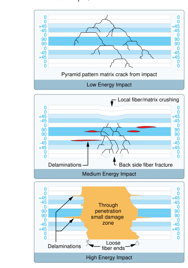
Modern aircraft rely heavily on composite materials—carbon fiber, fiberglass, Kevlar, and hybrid laminates—for everything from control surfaces to primary fuselage panels. Unlike aluminum, which dents and cracks visibly, composite structures can absorb a significant impact and look perfectly intact on the surface while hiding dangerous internal damage. Delaminations, disbonds, voids, and matrix cracks can all lurk beneath an undamaged exterior layer, silently compromising the load-carrying ability of a critical component. For the aviation maintenance technician, this makes systematic, informed inspection of composite structures one of the most important skills on the shop floor.
This article walks through the full framework for composite damage assessment: what types of damage occur, why they matter structurally, which inspection methods are available and when each is appropriate, and the regulatory and manufacturer-guidance context that governs the whole process. Whether you are working toward your FAA AMT General knowledge test or preparing for your first hands-on composite repair, this material will give you a solid foundation.
Understanding Composite Damage Types
Before choosing an inspection method, a technician must understand what kinds of damage are possible in a laminated composite structure. The FAA's Aviation Maintenance Technician Handbook—General (FAA-H-8083-30) groups composite damage into several broad categories:
- Delamination: A separation between two adjacent plies within the laminate. Delaminations are among the most serious defects because they interrupt the load path between layers. They can originate from manufacturing voids, moisture absorption and freeze-thaw cycling, or impact events. Even a moderate delamination can allow ply buckling under compressive load.
- Disbond: A separation at the adhesive interface between a skin and a core material (such as honeycomb or foam), or between two bonded structural members. A disbonded skin panel is effectively unsupported and can rapidly propagate failure.
- Matrix cracking: Cracks within the resin system that run between fibers rather than through them. Matrix cracks may seem cosmetically minor, but they open pathways for moisture and chemicals to reach the fiber-resin interface and cause further degradation.
- Fiber breakage: Actual severing of the load-carrying fibers. This is the most structurally severe damage mode and is often the result of a hard impact. When fibers break, the local area loses a direct proportion of its tensile and compressive strength.
- Core damage: Crushing, cracking, or moisture saturation of honeycomb or foam core. A crushed core loses its ability to carry shear loads and to keep the skins in their correct relative positions. Moisture trapped in a honeycomb core is a recognized concern because it can freeze at altitude and expand, dramatically worsening the disbond over repeated flight cycles.
- Surface erosion and scratches: While less structurally critical, surface damage removes the protective coating and can accelerate UV and moisture degradation of the underlying matrix.
Why Damage Identification Is Uniquely Challenging in Composites
In metallic structures, inspectors look for visible deformation, corrosion, or cracks—clues the material displays on its surface. Composites, however, are inherently layered structures in which the outer plies can remain intact while inner plies or core bonds have completely failed. This happens because composite materials dissipate impact energy progressively through the laminate. An object that would dent an aluminum skin may instead shatter interior plies and leave the surface coat unmarked. The phenomenon is sometimes called barely visible impact damage (BVID)—a term used widely in the aerospace composite community to describe impact damage at the threshold of visual detectability that may still exceed structural limits. Manufacturers set BVID thresholds during certification testing, and those thresholds define the damage tolerance of the structure. Technicians must treat any suspected impact event as cause for thorough inspection even if no surface mark is present.
Inspection Methods
Visual Inspection
Visual inspection is always the first step. A good visual survey requires proper lighting—a bright flashlight or LED work light held at a low angle (raking light) can reveal surface waviness, resin-starved areas, shadowing, or slight depressions that otherwise disappear under direct overhead illumination. Magnifying lenses help identify fiber tearing, micro-cracks, or surface coating bubbles that signal underlying problems. Inspectors look for whitening (stress-whitening of the resin), discoloration from heat, blistering from moisture, or distortion of the weave pattern. Although visual inspection cannot detect subsurface delaminations, it identifies the search area for more sensitive methods and catches fiber breakage, edge delamination, and surface erosion reliably.
Tap Testing (Coin Tap)
Tap testing is arguably the most widely used field technique for detecting delaminations and disbonds in composite skins. The inspector taps the surface methodically with a small coin or a dedicated tap-test hammer and listens to the acoustic response. A solid, well-bonded laminate produces a sharp, high-pitched ring, while a delaminated or disbonded region returns a dull, flat thud—sometimes described as a hollow sound. The physics behind this are straightforward: a bonded laminate vibrates as a coupled system with high stiffness, producing a high-frequency resonance; a disbonded region vibrates as a free, unsupported plate at much lower frequency.
Tap testing is generally effective on thin composite skins and honeycomb sandwich structures, where even small disbonds create a noticeable acoustic change; FAA-H-8083-30 does not specify a precise thickness threshold, but as laminate thickness increases the method becomes less reliable because the outer plies can mask interior damage. Technicians must be systematic, using a grid pattern with overlapping coverage, and should establish a baseline sound from a known-good region before assessing suspect areas. FAA-H-8083-30 discusses tap testing (coin tapping) as a common field method for detecting disbonds and delaminations in composite structures; whether tap testing—or any inspection method—is appropriate for a specific aircraft and structure is ultimately determined by the applicable SRM or AMM, not by the handbook alone.
Ultrasonic Inspection
Ultrasonic testing (UT) sends high-frequency sound waves into the structure and measures either the time-of-flight reflection (pulse-echo) or the attenuation of transmission through the part (through-transmission). Pulse-echo techniques require access from one side only and can precisely locate the depth of a delamination within a laminate stack. Through-transmission ultrasonic (TTU) testing requires access from both sides but provides excellent sensitivity to voids and delaminations across large panel areas. Automated TTU scanners produce C-scan maps—essentially a color-coded plan-view image of the internal condition—that make it straightforward to measure the area and location of damage precisely. UT is the method of choice when a tap test or visual inspection identifies a suspect area and quantitative sizing is needed before a repair decision is made.
Thermographic Inspection
Infrared thermography (IRT) uses a thermal camera to detect how heat flows through a structure. A bonded, uniform laminate conducts heat evenly; a delamination or disbond is a poor thermal conductor and creates a warm or cool spot on the surface that the camera images. Flash thermography—a brief burst of heat from a lamp followed by time-resolved imaging—is fast, covers large areas, and requires only one-sided access. It is increasingly common in airline and military depot maintenance environments for rapid wide-area screening of composite fuselage panels and control surfaces.
Radiographic Inspection
X-ray radiography is effective for detecting core damage, water ingress in honeycomb cavities, and certain voids, because water and crushed core have different density characteristics than the surrounding structure. However, X-ray has limited sensitivity to planar defects (delaminations parallel to the film) and requires radiation safety precautions and regulatory controls. It is generally reserved for depot-level inspection or specific problems such as water-in-honeycomb detection.
Regulatory and Manufacturer Guidance Framework
No single FAA regulation specifies exactly how to inspect every composite part—the governing documents are the aircraft's approved maintenance manual (AMM) and the Structural Repair Manual (SRM). These manufacturer-produced documents, approved under the aircraft's type certificate, define allowable damage limits (ADL), damage classification criteria, and required inspection intervals. Before any composite inspection, the technician must identify the correct manual, the correct chapter, and the approved method for that specific structure. Deviating from the SRM without an engineering order or a designated engineering representative (DER) approval is not permissible.
Title 14 CFR Part 43 governs the performance of maintenance and requires that it be accomplished in accordance with the manufacturer's instructions or methods acceptable to the FAA Administrator. For composite repair, Advisory Circular AC 43.13-1B provides general acceptable methods, but for most certificated composite airframes, the manufacturer's SRM supersedes AC 43.13-1B where the two differ.
Key Numbers and Rules
- Tap test effectiveness: Generally reliable on thin solid laminates and honeycomb sandwich structures; FAA-H-8083-30 does not give a precise thickness threshold, and reliability decreases as laminate thickness increases.
- Allowable damage limits: Always defined per-aircraft in the SRM—never apply limits from one aircraft to another.
- Moisture sensitivity: Most epoxy-matrix composites absorb moisture over time; repairs made to moisture-saturated laminates without proper drying will have compromised bond strength. Many SRMs require pre-repair drying at specified temperature and time.
- Part 43 requirement: All inspections and repairs must be properly documented in the aircraft maintenance records per 14 CFR §43.9.
- Delamination vs. disbond: Delamination is ply-to-ply separation within a laminate; disbond is failure of an adhesive bond between a skin and core or between two separate bonded parts. The distinction matters because repair methods differ.
Common Test Traps
- Confusing delamination with disbond: FAA knowledge-test questions often probe whether a candidate knows the difference. Remember: delamination is internal to the laminate; disbond is at a bond-line between dissimilar elements.
- Assuming tap testing works on all thicknesses: Tap testing is not reliable on thick solid laminates. Ultrasonic testing is required for quantitative assessment of deep damage.
- Ignoring BVID: A structurally significant impact may leave no visible mark. Any reported or suspected impact event warrants more than a visual check—always follow the SRM inspection sequence.
- Applying AC 43.13-1B universally: AC 43.13-1B provides general guidance, but the manufacturer's SRM is the controlling document for certificated composite airframes and takes precedence where it provides more specific guidance.
- Skipping moisture drying before repair: Attempting a bonded repair on a wet or moisture-saturated laminate is a common mistake. Moisture outgasses during cure and creates voids in the repair bondline. The SRM specifies drying procedures that must be followed before repair commences.