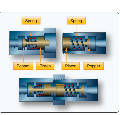
Aircraft fluid systems — hydraulic, fuel, oil, and pneumatic — depend on hundreds of fittings to route fluid safely from one component to another. Among the most useful of these are quick-disconnect fittings, engineered to allow technicians (and sometimes flight crew) to connect or separate fluid lines quickly, cleanly, and without specialized tools. When you pull an engine for overhaul, swap a hydraulic actuator, or change a filter element that sits on a removable module, quick-disconnect fittings make the job dramatically faster and reduce the risk of contamination. Understanding their design, operating principles, and inspection requirements falls within the Fluid Lines and Fittings knowledge area of the FAA Aviation Mechanic — General knowledge examination and is fundamental to safe aircraft maintenance.
This article covers the main types of quick-disconnect fittings found in aviation, explains exactly how each type seals and releases, and walks through the maintenance and inspection tasks an AMT is expected to perform. Fluid Lines and Fittings is one of the core knowledge areas for the General test, so mastering this topic pays dividends both in the exam room and in the hangar.
What Makes a Fitting "Quick-Disconnect"
A conventional threaded fitting requires the technician to rotate the coupling nut many times to mate or break a connection, and fluid will spill unless the system is first depressurized and drained. A quick-disconnect fitting, by contrast, incorporates an automatic shutoff valve inside each half of the coupling. When the two halves are separated, a spring-loaded poppet or sleeve slides into the closed position in each half almost simultaneously, trapping fluid on both sides and preventing spillage. When the halves are reconnected, the poppets are mechanically pushed open, restoring full flow. This two-valve, self-sealing design is the defining feature of all aviation quick-disconnect fittings.
The coupling action itself can be accomplished by a simple push-and-turn (bayonet style), a pull-back collar (sleeve-locking style), or a threaded ring that engages in only one or two turns. In every case the goal is the same: secure, leak-free connection with minimal effort and minimal fluid loss during disconnection.
Common Types of Quick-Disconnect Fittings
Poppet-Type (Self-Sealing) Couplings
The poppet-type is the most widely used design in aircraft hydraulic and fuel systems. Each half of the fitting contains a spring-loaded poppet valve. In the disconnected state, system pressure and spring force hold each poppet firmly against its seat, producing a positive seal. When the two halves are pushed together, the poppet stems contact each other and are forced back off their seats, opening both valves simultaneously and allowing fluid to flow through the coupled assembly. An outer locking sleeve — often incorporating a detent ball arrangement — snaps into place to keep the halves joined under pressure. To disconnect, the technician pulls back the locking sleeve and pulls the halves apart; the springs immediately close both poppets before significant fluid can escape.
Because both halves seal independently, poppet-type fittings dramatically reduce fluid loss and air ingestion during maintenance. This matters especially in hydraulic systems, where even a small air bubble can cause erratic actuator movement or spongy controls.
Sleeve-Type (Straight-Through) Couplings
Some low-pressure or instrumentation lines use a sleeve-type quick-disconnect where the sealing is accomplished by an O-ring or face seal rather than a poppet. These fittings may not be self-sealing in both directions and are therefore restricted to applications where the line can be de-pressurized and drained before disconnection. The outer locking collar, when retracted, releases the inner nipple so the connection can be broken quickly — hence the "quick-disconnect" label — but the technician must manage fluid spillage. These are less common in primary hydraulic or fuel circuits but appear in oxygen systems and some instrumentation tubing runs.
Dry-Break Couplings
High-performance aircraft and some military designs use dry-break couplings, an enhanced version of the poppet design engineered to produce virtually zero fluid loss — a "dry break" — when disconnected even under residual system pressure. The valving geometry and spring forces are precisely matched so the two poppets close before any measurable fluid exits. Dry-break couplings are common at pressure refueling points and in aircraft that use on-board oxygen generating systems (OBOGS) or other fluid systems where even trace contamination is unacceptable.
Ball-Lock and Bayonet Couplings
Some designs use detent balls riding in a groove on the male nipple to lock the fitting together, rather than a threaded ring or sliding collar. Others use a bayonet arrangement — lugs on the male half that engage slots in the female half with a quarter-turn. Both styles provide fast connection and positive locking, and both can be combined with internal poppets for self-sealing operation. You will find bayonet-style quick-disconnects frequently in aircraft oxygen plumbing and in some pneumatic de-ice system lines.
Identification and Compatibility
Quick-disconnect fittings are not interchangeable across manufacturers or ratings unless specifically certified as compatible. Each fitting carries markings indicating the manufacturer, part number, working pressure, and often a dash number indicating tube or hose size. The manufacturer's Aircraft Maintenance Manual (AMM) and Illustrated Parts Catalog (IPC) for the specific aircraft must be consulted to identify the correct replacement fitting. Mixing incompatible halves is a critical error: the poppets may not open fully, reducing flow area, or the locking mechanism may engage incompletely, leading to an in-service separation. Always verify that the replacement fitting is the approved part or an approved equivalent.
Why Quick-Disconnect Fittings Matter
Beyond maintenance convenience, these fittings serve genuine safety roles. In an emergency ground egress scenario involving a quick-release fuel coupling, the system can be broken down faster, reducing fire risk. More practically, self-sealing hydraulic fittings prevent system depressurization and contamination entry during component changes on the flight line. Contamination — dirt, moisture, or air — is the leading cause of hydraulic component failure, so any fitting that limits exposure to the environment when a line is open provides a real reliability benefit.
From an examination standpoint, the FAA expects AMT candidates to understand that quick-disconnect fittings are not immune to leakage, wear, or improper installation. The convenience they offer must not lead to casual or uninspected maintenance practices.
Key Numbers and Rules
- Both halves must be inspected separately and together. A worn or damaged poppet in one half can allow internal leakage even when the fitting appears coupled and locked.
- O-rings and seals are time- and cycle-limited components. Replace them at intervals specified in the AMM; do not defer seal replacement simply because the fitting shows no external leak yet.
- Working pressure ratings must meet or exceed the system's maximum operating pressure plus surge allowances. Never substitute a lower-rated fitting.
- Locking mechanisms must be tested by attempting to pull the coupling apart after connection — the fitting should resist separation and require deliberate actuation of the release collar or sleeve.
- Torque and installation: The threaded end that attaches the fitting body to the tube or manifold must be torqued to the value in the AMM. Over-torquing can crack the fitting body; under-torquing can allow rotation and leakage at the back ferrule.
- Fluid compatibility: Seals within quick-disconnect fittings are compounded for a specific fluid type (e.g., MIL-PRF-5606 hydraulic fluid, aviation gasoline, Skydrol). Using a fitting in the wrong fluid type will degrade the seals rapidly and cause contamination of the system fluid.
Maintenance and Inspection Procedures
When inspecting quick-disconnect fittings during a scheduled inspection, an AMT should follow these steps: First, verify the locking mechanism engages positively — pull on the connected halves without releasing the collar; there should be no play or tendency to separate. Second, inspect the exterior for corrosion, cracks, dents, and evidence of chafing. Aluminum fittings used in hydraulic systems are particularly susceptible to galvanic corrosion if in contact with dissimilar metals without proper protective coating. Third, check for external weeping around the coupling joint. Even a very small wet spot indicates seal deterioration and warrants immediate disassembly and seal replacement. Fourth, after any disconnection and reconnection, perform a pressure test per the AMM — typically by pressurizing the system to normal operating pressure and inspecting for leaks with a clean cloth or approved leak detector fluid. Finally, cycle the fitting (connect and disconnect) the number of times specified in the maintenance procedure to verify smooth operation of the locking collar and poppets. Rough or stiff operation indicates contamination or internal corrosion inside the fitting body.
When replacing seals, always clean mating surfaces carefully, lubricate new O-rings with the system fluid (not grease, unless specifically called for), and ensure the replacement seal is from an approved part number. Document all maintenance actions in the aircraft records per 14 CFR 43.9 and 43.11, and retain records per 14 CFR 91.417.
Common Test Traps
- Assuming self-sealing means zero spillage. The FAA tests whether you understand that poppet-type fittings minimize but may not completely eliminate fluid loss during disconnection — especially if residual pressure remains in the line. Always depressurize when possible.
- Confusing coupling halves. The male (nipple) and female (body) halves of a quick-disconnect fitting are not the same part. Ordering or installing the wrong half is a common maintenance error. The IPC will show both halves with separate part numbers.
- Overlooking fluid compatibility. Test questions sometimes present a scenario where a fitting is technically the correct size and pressure rating but has seals compounded for the wrong fluid. This is an airworthiness defect even if the fitting shows no immediate leakage.
- Neglecting the locking pull-test. Many technicians visually confirm the collar snapped but do not physically attempt to separate the halves. The FAA expects a positive pull-test as part of proper installation verification.
- Mixing manufacturer fittings. Two quick-disconnect fittings that look identical and appear to couple may not be rated to the same pressure or have the same poppet geometry. Mixing brands without cross-reference documentation in the AMM is an unapproved practice.