Directional control in an aircraft is achieved through two closely related but functionally distinct systems: the rudder, which provides yaw control in flight, and the nose wheel steering system, which guides the aircraft during taxi, takeoff roll, and landing rollout. For an AMT working on airframe assembly and rigging, understanding how these systems are set up, adjusted, and verified is essential — misrigged rudder or steering components can introduce dangerous handling characteristics that may not become obvious until a critical phase of flight or ground operation.
This article covers the mechanical principles behind both systems, the rigging procedures used in practice, the critical measurements and tolerances that must be verified, and the test traps that appear on the FAA AMT Airframe Knowledge Test.
How the Rudder System Works
The rudder is a movable control surface attached to the trailing edge of the vertical stabilizer by hinge points. When the pilot pushes a rudder pedal, a system of cables, pulleys, bellcranks, or pushrods transmits that force to the rudder horn, rotating the rudder about its hinge line. This deflection generates an aerodynamic force that yaws the aircraft about its vertical axis.
Most light aircraft use a cable-and-pulley system to connect the rudder pedals to the rudder. The two cables — one for left deflection and one for right — are routed through the fuselage, over pulleys, and attached to the rudder horn on either side. Some aircraft use a single cable with a return spring, while turbine aircraft and some high-performance designs may use push-pull rods or hydraulic actuation. Regardless of the mechanism, the rigging goal is the same: full, symmetric deflection with no binding, no excessive play, and correct cable tension throughout the range of travel.
Rudder Neutral Position
Before adjusting travel stops or cable tension, the technician must establish and verify the neutral position of the rudder. The neutral position is defined in the aircraft's maintenance manual (MM) and Type Certificate Data Sheet (TCDS) — typically, the rudder trailing edge is aligned with the trailing edge of the vertical stabilizer, and the pedals are centered. Rigging jigs or alignment fixtures specified by the manufacturer are used to lock the control surface in neutral while cables are adjusted. Using a protractor, inclinometer, or rigging board, the technician confirms the surface is at zero deflection (0°) or within the tolerance stated in the MM before proceeding.
Rudder Cable Tension and Travel Limits
Cable tension is one of the most critical variables in rudder rigging. Too little tension allows slack that introduces control lag and can permit cables to jump off pulleys under flight loads. Too much tension creates excessive bearing wear, stretches cables prematurely, and may prevent full deflection because the taut cables resist movement. Cable tension must always be measured with a calibrated tensiometer and corrected for ambient temperature, because steel cables expand and contract with temperature changes. The MM provides a tension chart that cross-references temperature and cable diameter to the correct tension range.
After confirming neutral position and correct cable tension, the technician checks travel limits — the maximum allowable rudder deflection in each direction. These limits are published in the MM and the TCDS and vary considerably by aircraft design; the exact values must always be verified against the specific aircraft documentation, never assumed or applied generically from another type. Travel is measured with a protractor or rigging board at the control surface itself, not at the pedal. Mechanical stops — either adjustable bolts or fixed hard stops in the system — prevent the surface from exceeding its design limits. When adjusting stops, the technician verifies that the stop is contacted before the cable or any linkage component reaches a binding condition, because binding can damage fittings and prevent the pilot from releasing the control.
Checking for Symmetry
A correctly rigged rudder system produces equal travel in both directions. The technician measures left and right deflection separately and compares them against the MM specification. An asymmetric system — for example, 28° right and 24° left — indicates a problem such as unequal cable tension, an improperly centered turnbuckle, or a misaligned bellcrank. Asymmetric travel creates a tendency for the aircraft to yaw preferentially in one direction, which is particularly dangerous during the takeoff roll and initial climb.
Nose Wheel Steering System
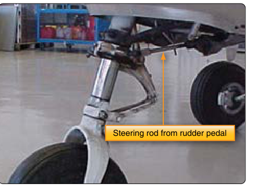
On tricycle-gear aircraft, the nose wheel steering system provides positive directional control while the aircraft is on the ground and aerodynamic rudder authority is insufficient — particularly at low taxi speeds. The most common design on light aircraft is a direct mechanical linkage between the rudder pedals and the nose gear steering collar or torque links, so that pressing a rudder pedal simultaneously deflects the rudder and turns the nose wheel. Some aircraft add a separate, dedicated tiller for greater steering authority during slow-speed maneuvering, and many transport-category aircraft use hydraulic nose wheel steering systems with their own dedicated actuators.
The nose gear assembly typically includes torque links (sometimes called scissors links) that prevent the nose strut barrel from rotating freely while still allowing the strut to compress and extend. Steering input is transmitted through a steering collar that rotates the outer strut barrel, and the torque links ensure the nose wheel turns with it. Misaligned or improperly rigged torque links can cause shimmy, nose gear vibration, and uneven tire wear.
Nose Wheel Centering and Alignment
Before rigging the steering system, the nose wheel must be verified to track straight ahead when the steering linkage is in its centered (neutral) position. The nose wheel alignment is checked by confirming the wheel is parallel to the aircraft centerline. Most aircraft use a centering cam within the nose gear strut that automatically aligns the wheel when the aircraft becomes airborne and the strut extends to its full length — this prevents the nose wheel from touching down in a turned position. During rigging, the technician must verify that this cam functions correctly and that the wheel self-centers on strut extension.
The steering linkage connecting the rudder pedals to the nose gear is adjusted so that full left pedal produces the maximum allowable nose wheel deflection to the left, and full right pedal produces maximum deflection to the right, with the limits being equal in both directions. Nose wheel steering travel limits vary significantly by aircraft type and design and are not standardized to a general range — the exact limits are found only in the MM and TCDS for the specific aircraft. Exceeding design limits places side loads on the nose gear that can damage the strut, torque links, and firewall attachment structure.
Why Correct Rigging Matters
The consequences of improperly rigged rudder or nose wheel steering are serious. In flight, a rudder with insufficient travel prevents the pilot from correcting asymmetric thrust on a multi-engine aircraft during engine failure — the FAA references this directly in engine-out control discussions. On the ground, a misrigged nose wheel system can cause loss of directional control during high-speed ground operations, leading to runway excursions. A binding rudder can make recovery from unusual attitudes impossible. For the AMT, these are not abstract concerns — improper rigging has contributed to accidents in the NTSB record.
Key Numbers and Rules
- Cable tension: Always measured with a tensiometer and corrected for temperature using the manufacturer's tension-temperature chart.
- Control surface neutral: Established using manufacturer-specified rigging fixtures before any tension or stop adjustments are made.
- Travel limits: Found in the MM and TCDS; measured at the surface with a protractor or rigging board — not estimated at the pedal.
- Symmetry: Left and right travel must match within the tolerance stated in the MM; asymmetry indicates a rigging error.
- Turnbuckles: After adjustment, must be safety-locked (wire or clip) per the applicable inspection criteria, with no more than three threads visible beyond the barrel on each end per AC 43.13-1B guidance — always verify against the specific chart or manufacturer data; this is a standard post-rigging inspection item.
- Centering cam: Must be verified functional; prevents landing with a deflected nose wheel.
- Documentation: All rigging work must be recorded in the aircraft maintenance records per 14 CFR Part 43.
Common Test Traps
- Confusing measurement location: FAA test questions sometimes ask where control surface travel is measured. The correct answer is at the surface itself, not at the pedal or cockpit control — measuring at the pedal does not account for mechanical advantage variations in the linkage.
- Ignoring temperature correction: Cable tension specifications are temperature-dependent. As temperature rises, cables expand and tension decreases, so a cable tensioned correctly at 30°F will be under-tensioned at 100°F. Forgetting to apply the temperature-tension correction chart is a common mistake and a tested concept.
- Assuming equal travel without checking: Students sometimes assume that if one direction is correct, the other must be too. The FAA expects technicians to measure each direction independently.
- Turnbuckle safety wire direction: FAA test questions probe knowledge of proper turnbuckle safetying methods. Both the single-wrap and double-wrap methods are acceptable; the key requirement is that the wire prevents the turnbuckle barrel from rotating in the loosening direction.
- Rigging sequence: The correct sequence is: establish neutral → set cable tension → check travel limits → verify symmetry → safety turnbuckles → document. Performing steps out of order (such as setting stops before establishing neutral) will produce an incorrectly rigged system even if every individual measurement is within tolerance.