Landing gear alignment and rigging are among the most critical maintenance procedures performed on an aircraft. Whether working on a simple fixed-gear trainer or a complex retractable system, the technician must ensure that all gear components — wheels, struts, actuators, and linkages — are positioned and adjusted so the aircraft tracks straight, rolls smoothly, and absorbs landing loads without imposing excessive stress on the airframe. Getting these procedures right is a foundational skill for every airframe technician, and the Federal Aviation Administration tests AMT candidates on both the theory and the practical steps involved.
This article walks through the principles of landing gear geometry, the step-by-step logic of alignment and rigging checks, and the critical specifications a technician must observe. Understanding not just what to do but why each adjustment matters will help you perform the job safely and ace the AMT Airframe knowledge test.
Landing Gear Geometry Fundamentals
Before any rigging work begins, a technician must understand the key geometry angles that define how a main gear or nose gear contacts the runway. These angles are defined in the aircraft's Type Certificate Data Sheet (TCDS) and the manufacturer's maintenance manual, and no adjustment should ever be made without consulting those documents first.
- Camber — The tilt of the wheel and tire assembly relative to a true vertical line when viewed from the front or rear of the aircraft. Positive camber means the top of the wheel leans outward; negative camber means it leans inward. Most light aircraft are designed with a small amount of positive camber when the aircraft is at its design gross weight. Incorrect camber causes uneven tire wear across the tread width and, on retractable gear, can prevent proper gear-door clearance.
- Toe-in and Toe-out — The angular relationship of the wheel's centerline to the aircraft's longitudinal axis when viewed from above. Toe-in means the leading edges of both main wheels point slightly toward each other; toe-out means they splay apart. Many aircraft are designed with a slight amount of toe-out to compensate for the tendency of wheels to toe-in under rolling loads, though the exact design intent varies by manufacturer and must always be verified against the specific maintenance manual. Excessive toe-in or toe-out causes rapid and uneven tire wear, generates heat in the tires and bearings, and produces lateral forces that stress landing gear attach fittings.
- Tread — The lateral distance between the centerlines of the two main gear wheels. This is a fixed design dimension; the technician does not adjust it, but checks it as part of confirming proper gear installation.
- Rake or Caster Angle (Nose Gear) — On nose gear assemblies, the angle of the steering axis relative to vertical. Proper rake angle affects self-centering behavior and ground steering stability. Shimmy — the rapid, uncontrolled oscillation of the nose wheel — is often related to improper nose gear geometry, worn shimmy dampers, or incorrect tire pressure rather than rigging error, but a technician must understand the relationship between geometry and shimmy tendency.
Rigging: What It Means and When It Is Required
In aviation maintenance, rigging refers to the adjustment and alignment of an aircraft's control systems or structural components to meet manufacturer specifications. For landing gear, rigging encompasses the adjustment of actuator travel, up-lock and down-lock engagement, gear door sequencing, warning horn and indicator switch settings, and the physical alignment of the gear legs themselves.
Rigging is required whenever: a gear component or attach fitting has been replaced; a hard or overweight landing has occurred that may have shifted gear geometry; the aircraft has experienced a gear-up landing or gear collapse; or an inspection reveals that wear or corrosion has changed the fit of components. Routine inspections also include a check of rigging parameters, since vibration and normal use can cause adjustable rod ends and jam nuts to migrate over time.
Alignment and Rigging Procedures Step by Step
1. Prepare the Aircraft and Consult Documentation
Always begin by reviewing the applicable sections of the manufacturer's maintenance manual. Locate the exact alignment specifications — camber angle in degrees, toe-in measurement in inches or degrees at the wheel rim, and actuator travel limits in inches or degrees of rotation. Place the aircraft on a level surface or use precision jacks to position it at the manufacturer-specified attitude. Many alignment checks must be performed with the aircraft at a specific weight or with ballast added to simulate that weight, because strut extension changes with load and directly affects gear geometry.
2. Inspect for Wear and Damage Before Adjusting
Alignment cannot be corrected if the underlying components are worn beyond limits. Before making any adjustment, inspect all rod end bearings for slop, all bolts for proper torque, all shimmy dampers for correct fluid level and damping action, and all structural attach points for cracks or deformation. An alignment check on worn components will give false results and mask problems that will reappear — or worsen — immediately after the aircraft returns to service.
3. Check and Adjust Camber
Using a plumb bob, precision digital level, or manufacturer-specified alignment tool, measure the camber angle at the wheel. Compare the measured value against the TCDS or maintenance manual specification. On many light aircraft, camber is not field-adjustable — it is set by the design of the gear leg and can only change if the leg is bent or the attach fittings are worn. On aircraft with adjustable gear, camber is corrected by shimming the gear attachment or adjusting eccentric bushings, depending on design. Always re-torque all fasteners after adjustment and recheck the measurement before signing off the work.
4. Check and Adjust Toe-In or Toe-Out
Toe is typically measured by placing a straightedge or string line along the outboard face of each tire and measuring the convergence or divergence at a set distance in front of and behind the axle centerline. The difference in those two measurements gives the toe value. On many fixed-gear aircraft, toe is adjusted by changing the length of the radius rod or drag brace — the fore-and-aft link that prevents the gear from swinging forward or rearward under load. Shortening or lengthening this rod, via threaded rod ends, changes toe angle. After adjustment, secure all jam nuts and recheck.
5. Rig Retractable Gear Actuator Travel and Locks
For retractable landing gear systems, rigging also involves setting the precise travel of hydraulic or electric actuators so that the gear reaches the fully down-and-locked or fully up-and-locked position correctly. Down-locks must engage with a positive mechanical overcenter or latch before the system pressure is removed. If a down-lock engages too late in the travel, the gear may appear down but will collapse under load. Up-locks must hold the gear securely retracted against aerodynamic loads and vibration. The technician adjusts actuator stroke, linkage rod lengths, and lock engagement points to achieve the exact overcenter or latch geometry specified by the manufacturer, then verifies proper operation through multiple cycles on the jack.
6. Set Gear Position Indicator and Warning Horn Switches
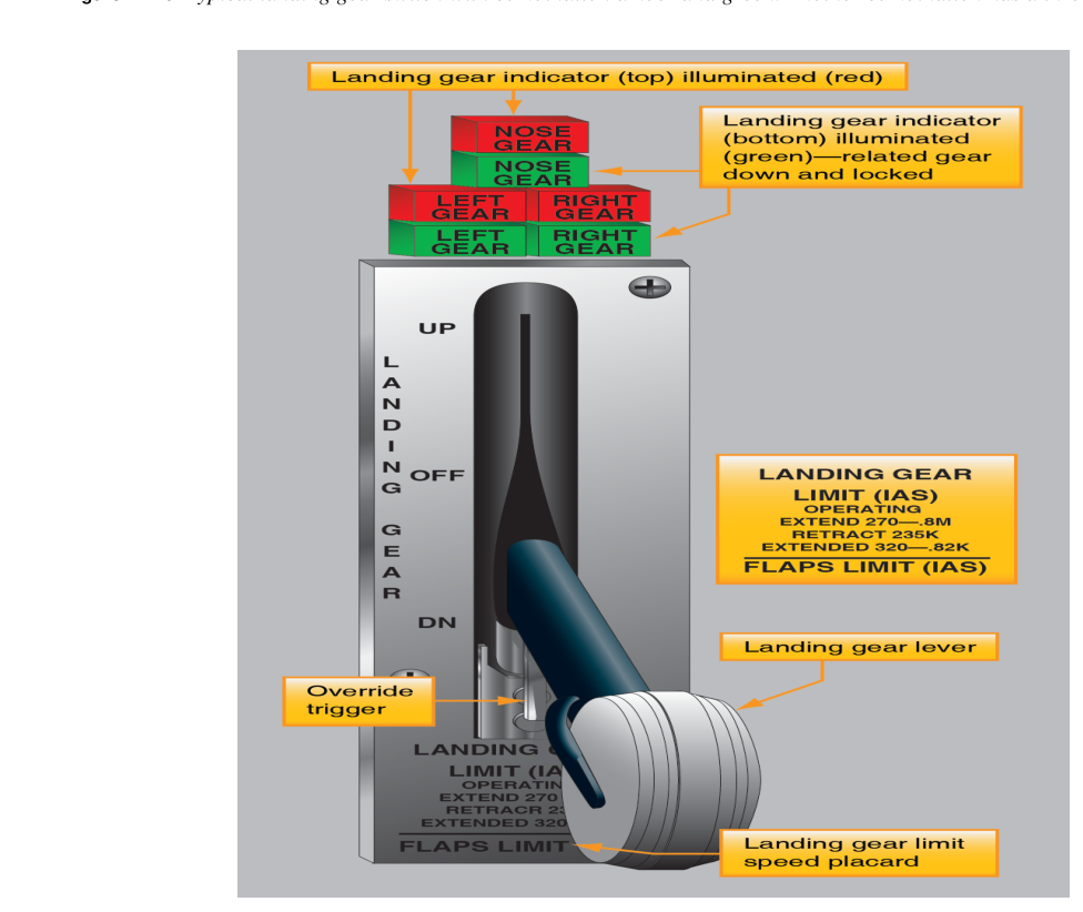
Gear position switches must be rigged so that the cockpit indicator shows DOWN AND LOCKED only when the gear is truly mechanically locked down, and the warning horn activates at the correct throttle setting or flap position when the gear is not down. These switches are typically adjusted by loosening a mounting bracket and sliding the switch until the electrical transition point coincides with the mechanical lock engagement point. An improperly rigged switch can give a false DOWN indication with the gear not fully locked — an extremely dangerous condition.
Why Alignment and Rigging Matter
Improper landing gear alignment creates a cascade of problems. Incorrect toe-in causes tire scrubbing that generates heat, accelerates wear, and can lead to blowouts. Bent or misaligned gear legs impose bending moments on their attach fittings with every landing, eventually causing fatigue cracking. Misrigged retractable gear may collapse on landing if the down-lock does not achieve proper overcenter position. In the worst cases, gear-related failures have caused fatal accidents. Thorough, documented rigging performed to manufacturer specifications — and confirmed through repeated ground cycles before flight — is a non-negotiable safety requirement.
Key Numbers and Rules
- All alignment specifications come from the manufacturer's maintenance manual and the TCDS — there are no universal values; always use the aircraft-specific document.
- Aircraft must be placed at the manufacturer-specified weight and attitude (often using prescribed jack points and a level reference) before alignment measurements are taken.
- After any adjustment involving threaded rod ends or jam nuts, re-torque to specification and apply torque seal or safety wire per the manual.
- Retractable gear rigging must be verified through multiple complete cycles on the jack before return to service, with the exact number of cycles specified by the manufacturer's maintenance manual — there is no single FAA-mandated numeric standard.
- Any work on gear systems that affects airworthiness must be documented in the aircraft maintenance records per 14 CFR Part 43.
- A return-to-service sign-off for landing gear rigging requires an appropriately rated Airframe (or A&P) mechanic or a certificated Repair Station with appropriate ratings.
Common Test Traps
- Confusing toe-in with camber. Toe is measured in the horizontal plane (viewed from above); camber is measured in the vertical plane (viewed from the front). The FAA knowledge test presents questions with diagrams — study both angles carefully.
- Assuming one specification fits all aircraft. There is no single correct toe value or camber angle for all aircraft. The test may present a scenario where the student must recognize that the manufacturer's manual — not a general rule — is the authoritative source.
- Overlooking the weight and attitude requirement. Strut compression changes gear geometry. A measurement taken with the aircraft improperly loaded or not level will be meaningless. Test questions frequently test whether candidates know that alignment must be checked at the specified weight.
- Misunderstanding overcenter locks. A down-lock that engages mechanically overcenter is locked by geometry, not by hydraulic pressure. If you remove hydraulic pressure and the gear collapses, the lock is not properly rigged — not a hydraulic problem. The AMT test exploits confusion between hydraulic loading and mechanical locking.
- Forgetting documentation requirements. Even a perfect alignment job is incomplete if it is not properly recorded in the maintenance records as required by 14 CFR Part 43. Questions about the sign-off requirement and what must be recorded appear regularly on the AMT Airframe test.