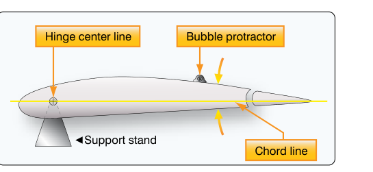
When an airframe technician completes a control surface repair, replacement, or reassembly, the job is not finished until every surface is verified to move the correct amount, in the correct direction, and returns precisely to its neutral position. Flight control alignment and neutral position setting — collectively part of the broader discipline of aircraft rigging — are among the most safety-critical tasks in airframe maintenance. An improperly rigged aileron can cause a persistent roll tendency; a misaligned elevator can make the aircraft uncontrollable at critical speeds; a rudder that does not return to neutral can introduce hazardous yaw during approach and landing. Understanding the theory, procedure, and acceptance criteria for these checks is essential for any Airframe Mechanic certificate holder.
This article covers the principles behind control surface neutral position, the methods used to establish and verify alignment, travel limits, and the regulatory framework that governs the process. It is grounded in the Aviation Maintenance Technician Handbook — Airframe (FAA-H-8083-31) and the applicable 14 CFR requirements.
What Is Neutral Position and Why Does It Matter?
The neutral position of a flight control surface is the specific deflection angle — usually zero degrees relative to a defined reference — at which the surface produces no aerodynamic moment about the hinge line beyond what the baseline airfoil already generates. For most primary surfaces, neutral means the control surface chord is aligned with, or forms a specified small angle to, the fixed surface chord or a waterline reference. For trim tabs, neutral is typically the position at which no trimming moment is applied to the primary surface.
Neutral is important for two distinct reasons. First, it is the geometric starting point from which all travel limits are measured. If the surface is rigged 2° nose-up instead of true neutral, the up-travel limit will effectively be 2° less than design and the down-travel limit will be 2° more, skewing control authority and potentially inducing flutter or structural overload at one extreme. Second, the neutral position correlates directly to the cockpit control's center (or trim indicator's zero). A mismatch causes the aircraft to fly with a chronic control input or trim offset, degrading efficiency and masking the feel cues the pilot relies on.
How Rigging Works: The Core Mechanics
Reference Datums and Rigging Templates
Every aircraft manufacturer publishes a rigging specification — typically found in the Aircraft Maintenance Manual (AMM) and summarized in Type Certificate Data Sheets (TCDS) — that defines the neutral position and travel limits for each control surface. The AMT must identify the rigging datum for each surface before any measurement is taken. Common datums include:
- Waterline (WL) references — horizontal reference planes established during original design, used particularly for horizontal stabilizer incidence checks.
- Buttock line (BL) and fuselage station (FS) references — used to locate control components laterally and longitudinally.
- Fixed surface chord lines — a straight edge or straightedge placed along the stabilizer or wing fixed surface to which the movable surface is compared.
- Rigging pins and alignment fixtures — manufacturer-supplied tools that physically lock components in their defined neutral positions during assembly and cable adjustment.
Many manufacturers supply rigging templates — precisely machined cutouts or protractor fixtures that fit over the hinge axis and directly indicate surface angle. Using the correct, current template is mandatory; using a worn or incorrect tool can introduce systematic error across every measurement taken.
Cable Tension and Turnbuckle Adjustment
On cable-operated systems, the tension in each cable segment directly affects where the control surface rests when the cockpit control is centered and released. The AMM specifies cable tension values — typically in pounds — corrected for ambient temperature, because cable tension changes significantly with temperature due to differential thermal expansion between the aluminum airframe and steel cables. A cable that is correctly tensioned at 60 °F may be over-tensioned at 100 °F, binding the system and preventing full travel.
Adjustment is made at turnbuckles, which thread onto the cable ends. After adjustment, each turnbuckle must be safety-wired or clip-safetied so that no barrel thread is exposed beyond the allowable limit — FAA guidance generally requires that no more than three threads be exposed on each side of the barrel after safetying. Turnbuckle safety is not cosmetic; a turnbuckle that backs off in flight can produce catastrophic control loss.
Push-Pull Rod Systems
Many modern aircraft and virtually all composite designs route control loads through push-pull tubes rather than cables. Neutral position is established by threading rod-end bearings or clevis ends in or out on each tube until the surface aligns with the datum while the cockpit control is centered. Rod-end bearing thread engagement must meet the manufacturer's minimum — typically a full depth of engagement equal to the rod diameter — and is usually verified with a witness hole through which a drill bit or pin can be inserted to confirm proper thread engagement.
Measuring Travel
Once neutral is established, total travel is measured using a protractor, inclinometer, or digital angle gauge placed on a flat reference surface of the control surface — never on a curved surface or near a skin fastener. The cockpit control is moved to each stop, and the resulting surface angle is recorded. Measurements must fall within the tolerances published in the TCDS and AMM. Typical primary surface travels include:
- Ailerons: commonly 20–30° up and 15–25° down (differential travel is intentional and designed to minimize adverse yaw).
- Elevators: commonly 25–30° up and 20–25° down, measured from neutral.
- Rudder: commonly 25–35° left and right of neutral.
- Flaps: from 0° (retracted) to a manufacturer-specified full-down position, often 30–40° on general aviation aircraft.
Note that these values are illustrative; always defer to the specific TCDS and AMM for the aircraft being rigged. The TCDS is the legally controlling document under 14 CFR Part 21.
Trim Tab Rigging
Trim tabs introduce an additional layer of rigging because their neutral must be established relative to the primary surface neutral, not the fixed airfoil. When the primary surface is at its neutral and the cockpit trim indicator reads zero (or trim is centered), the trim tab must be at its own neutral — which may be flush with the primary surface or at a small specified angle depending on design. The AMT establishes primary surface neutral first, then adjusts the trim tab linkage with the trim control centered before measuring and setting trim tab travel.
Why This Matters: Safety and Airworthiness
Incorrect rigging has caused fatal accidents throughout aviation history. The consequences of misaligned control surfaces include:
- Reduced control authority — a surface already deflected away from neutral has less remaining travel in one direction, which may be critical during a go-around or crosswind landing.
- Flutter — incorrect mass balance or hinge moment resulting from off-neutral rigging can lower the flutter onset speed below the aircraft's operational envelope.
- Asymmetric handling — ailerons not rigged to matching neutral positions cause the aircraft to require continuous control input, fatiguing the pilot and masking other discrepancies.
- Trim runaway amplification — a trim tab at an incorrect neutral position effectively shifts the entire trim range, potentially allowing an uncommanded nose-up or nose-down configuration that exceeds the primary surface's corrective authority.
Under 14 CFR Part 43, any person who performs maintenance that could affect the flight characteristics of an aircraft must return it to its original or properly altered condition and must make the appropriate logbook entry. Flight control rigging squarely falls under this requirement, and a return-to-service entry must reference the AMM procedures used and confirm that travel limits were verified.
Key Numbers and Rules
- Control surface travel must match TCDS-published limits; deviations require an approved data source (STC, FAA field approval, or manufacturer deviation approval).
- Cable tension must be corrected for temperature using the chart in the AMM; never set tension without knowing ambient temperature.
- Turnbuckle thread exposure: no more than three threads visible on each side after safetying.
- Rod-end bearing engagement: minimum full-diameter thread engagement per AMM (verify via witness hole).
- Rigging checks are required after: control surface replacement, cable replacement, turnbuckle replacement, structural repair in the control circuit area, and any time abnormal loads or a hard landing may have affected the control system.
- Rigging work must be documented under 14 CFR 43.9 and 43.11 recordkeeping requirements; if the rigging task involves a major repair or alteration as classified under Part 43, Appendix A, it must be recorded on FAA Form 337 per the process described in Appendix B.
Common Test Traps
- Measuring from the wrong datum. Students often confuse the waterline datum with the chord line datum. Always identify which reference the AMM specifies before placing any measuring tool on the surface.
- Ignoring temperature correction for cable tension. A cable tensioned correctly at a cold morning temperature may be dangerously over-tensioned by afternoon. Test questions frequently present a scenario where cable tension was set without temperature correction.
- Assuming symmetrical aileron travel. Ailerons are intentionally rigged with differential travel — up travel is greater than down travel — to minimize adverse yaw. Assuming equal travel in both directions is a common incorrect answer.
- Confusing primary surface neutral with trim tab neutral. Trim tab neutral is set with the primary surface at neutral AND with the cockpit trim indicator at its zero or centered position, not independently.
- Overlooking thread engagement on rod-end bearings. Turnbuckle safety-wiring gets attention, but rod-end bearing minimum engagement is equally critical and equally tested. Confirm via witness hole, not by visual inspection alone.