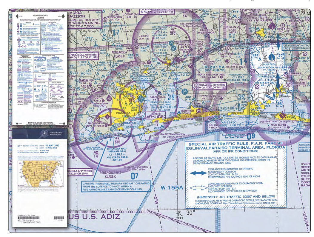
Sectional aeronautical charts are the primary visual reference tool for understanding the airspace environment in the United States. Whether you are a manned aircraft pilot or a Part 107 certificated remote pilot, the ability to read a sectional chart accurately is not just a knowledge-test requirement—it is a fundamental safety skill. Sectional charts are published by the Federal Aviation Administration (FAA) and distributed by the National Aeronautical Charting Office (NACO), with each chart covering a specific geographic region of the contiguous United States, Alaska, and Hawaii.
For the Part 107 Remote Pilot Certificate knowledge test, you will be expected to interpret chart symbols, understand chart scale, and extract critical airspace and obstacle information from a sectional chart. This article walks you through the scale, the legend, and the most important symbols you will encounter—explaining not just what each element looks like, but what it means operationally when you are planning a drone flight.
Chart Scale Explained
Every sectional aeronautical chart is drawn at a scale of 1:500,000. This means that one unit on the chart represents 500,000 of the same units on the ground. In practical terms, one inch on the chart equals approximately 6.86 nautical miles (roughly 7 statute miles) on the surface. This scale was chosen because it provides enough geographic coverage to be useful for cross-country navigation while still including sufficient detail to show airspace boundaries, airports, terrain features, and obstacles.
The name "sectional" comes from the fact that the contiguous United States is divided into sections, each chart covering one section. Each chart is updated on a 56-day cycle, making currency critically important. An outdated sectional chart may not reflect newly established airspace, new obstacles, or changed airport information. Part 107 remote pilots must use current charts because airspace constraints affect where and whether drone operations are legal without authorization.
The scale also has a practical implication when measuring distances. Chart edges include a graphic scale bar showing nautical miles, statute miles, and kilometers. If you need to determine how far a proposed flight site is from an airport or controlled airspace boundary, you can use the scale bar along with a ruler or the edge of a plotter to make that measurement directly on the chart.
How the Legend Is Organized
The sectional chart legend is printed in the chart margin (or on a separate legend card) and is the key to decoding every symbol on the chart. The legend is organized into logical categories, and understanding those categories makes reading the chart far more intuitive.
Airports
Airport symbols vary in shape, color, and interior detail to convey different types of facilities. The most important distinctions for Part 107 pilots are:
- Blue airports have an associated control tower operating at least part of the time (Class B, C, or D airports, or towered Class E surface airports). Operations within the airspace associated with these airports typically require prior authorization for drones.
- Magenta airports are non-towered airports. However, non-towered airports may still lie within Class E surface areas or Class E airspace starting at 700 feet AGL—both of which have implications for drone operations.
- A circle with a tick mark indicates a private or restricted airport.
- An airport symbol with an R inside indicates that prior permission is required from the airport owner.
Alongside the airport symbol, a data block provides the airport name, identifier, field elevation in feet MSL, control tower frequency (if applicable), ATIS frequency, and the longest runway length in hundreds of feet. For example, "34" in the data block means the longest runway is approximately 3,400 feet long.
Airspace Boundaries
Airspace is one of the most critical elements for Part 107 remote pilots. The chart uses distinct colors and line styles to depict different airspace classes:
- Class B airspace is depicted with solid blue lines forming concentric rings, resembling an upside-down wedding cake around major hub airports. Floor and ceiling altitudes are shown in hundreds of feet MSL (e.g., 40/SFC means from the surface to 4,000 feet MSL).
- Class C airspace uses solid magenta lines in a similar concentric ring pattern, typically with an inner and outer ring. The same altitude notation applies.
- Class D airspace is shown with a dashed blue line boundary around towered airports. It typically extends to 2,500 feet AGL.
- Class E surface areas (where Class E starts at the surface) use a dashed magenta line. These areas surround many instrument approach airports and require drone authorization for operations under Part 107.
- Class E airspace beginning at 700 feet AGL is depicted by a shaded magenta vignette—the color fades from solid magenta to the chart background moving away from an airport. This is commonly seen around smaller instrument-equipped airports and is easy to confuse with terrain shading.
- Class G airspace is not explicitly depicted on the chart; it exists wherever no other airspace class is defined, typically from the surface up to 700 or 1,200 feet AGL in most areas.
Obstacles and Terrain
The chart depicts man-made obstacles such as towers, wind turbines, and antenna farms using specific symbols. A single obstacle is shown with a filled triangle and altitude notations. The first number is the obstacle's height in feet MSL; the number in parentheses below or beside it is its height above ground level (AGL). For Part 107 operations, the AGL figure is the one that directly governs whether a structure creates a waiver need for flights above 400 feet AGL.
Groups of obstacles are shown with a cluster symbol. Particularly tall or hazardous obstacles (those exceeding 1,000 feet AGL) are depicted with a different symbol and may be highlighted in bold. High-tension power lines may or may not be shown depending on the chart edition—never assume a power line is absent just because it is not depicted.
Terrain elevation is communicated through contour lines (brown lines connecting points of equal elevation), color tinting (green for low terrain, progressing through tan and brown to gray for high terrain), and Maximum Elevation Figures (MEFs). MEFs appear in each latitude/longitude quadrant as large blue numbers and represent the highest terrain or obstacle within that quadrant, rounded up to the next 100-foot increment and then padded by 100 additional feet for safety. Remote pilots can use MEFs to quickly assess minimum safe altitudes for a given area.
Special Use Airspace and Other Restricted Areas
The legend also identifies Special Use Airspace (SUA), which includes:
- Restricted areas (depicted with blue hatched boundaries and labeled R-XXXX): flight may be prohibited or require ATC authorization when active.
- Prohibited areas (labeled P-XXXX): flight is not permitted at any time (e.g., P-56 over Washington, D.C.).
- Warning areas (labeled W-XXXX): similar to restricted areas but located over domestic and/or international waters.
- Military Operations Areas (MOAs): depicted with magenta hatching. Drone pilots should check MOA activity before flying; manned aircraft traffic may be intense and unpredictable.
- Alert areas: areas with high volumes of pilot training or unusual aerial activity, shown with blue hatching.
Why Chart Reading Matters for Part 107
Unlike manned aircraft pilots who primarily worry about airspace from a navigation and ATC communication standpoint, remote pilots must determine before they fly whether their proposed operating location falls within controlled airspace requiring FAA authorization via the LAANC system or a DroneZone waiver. A misread sectional chart could place a drone in Class D airspace near a busy general aviation airport without authorization, violating 14 CFR Part 107 and creating a genuine mid-air collision risk.
Accurate sectional chart reading also helps identify the presence of critical infrastructure, military training routes, and proximity to heliports—all of which affect safe drone operations. Heliports are shown as an H inside a circle; they often exist near hospitals, where drone operations must be conducted with heightened awareness of low-altitude air traffic.
Key Numbers and Rules
- Chart scale: 1:500,000 — one inch equals approximately 6.86 nautical miles.
- Update cycle: 56 days — always use a current chart for planning.
- Blue airport symbols = towered (controlled) airports; magenta = non-towered.
- Class D depicted with a dashed blue line; Class E surface areas with a dashed magenta line.
- Class E at 700 feet AGL uses a fading magenta vignette—not a sharp line.
- Obstacle data blocks show MSL altitude first, AGL altitude in parentheses.
- MEFs are the highest terrain or obstacle in a quadrant, rounded up and padded by 100 feet.
Common Test Traps
- Confusing Class D with Class E surface areas: Class D has a dashed blue border; Class E surface areas have a dashed magenta border. Mixing these up on the test leads to wrong airspace classification answers.
- Misreading the magenta vignette: The fading magenta shading around airports indicates Class E starting at 700 feet AGL—not terrain elevation or a prohibited area. Many students confuse this shading with topographic tinting.
- Ignoring the parenthetical AGL figure: The test will ask about obstacle height above ground. The MSL figure in the obstacle data block is irrelevant to the 400-foot AGL limit unless you know the terrain elevation; always look for the AGL number in parentheses.
- Assuming non-towered airports have no controlled airspace: Many non-towered airports have Class E surface areas (dashed magenta) or lie within Class E airspace starting at 700 feet AGL (magenta vignette), both of which require LAANC authorization for drone operations at many altitudes.
- Using an outdated chart: The 56-day update cycle is tested directly. An expired chart is not legally current for planning purposes and may show incorrect airspace depictions.