At first glance, an aircraft ignition switch looks like any ordinary on/off switch. Flip it on, the engine runs; flip it off, the engine stops. But the underlying electrical logic is exactly the opposite of what most people expect, and this counterintuitive design is one of the most important—and most frequently misunderstood—concepts in aircraft powerplant electrical systems. For AMT students preparing for the FAA Powerplant Knowledge Test, mastering ignition switch wiring and circuit protection is not just an academic exercise; it is a fundamental safety matter that affects every magneto-equipped aircraft in the world.
This article walks through how the ignition switch wiring works, why it is wired the way it is, what happens when that wiring fails, and what circuit protection measures exist to keep the system safe and reliable.
The Magneto Ignition System: A Quick Foundation
Aircraft piston engines use self-contained magneto ignition systems rather than battery-powered coil systems. A magneto is an engine-driven alternating-current generator that produces its own high-voltage electricity to fire spark plugs. Because a magneto generates its own power, the aircraft battery and master switch have no direct role in firing the spark plugs during normal operation. This design means the engine can run even when the battery is dead or the master switch is off—a critical safety and reliability feature.
Each engine is typically equipped with two magnetos—a left and a right—each firing one spark plug per cylinder. Dual ignition provides redundancy: if one magneto fails, the other keeps the engine running. It also improves combustion efficiency by igniting the fuel-air mixture from two points simultaneously.
How Ignition Switch Wiring Actually Works
Here is the counterintuitive core concept: the ignition switch does not supply power to the magnetos—it grounds them. Each magneto contains an internal primary circuit. When the primary circuit is allowed to complete its normal cycle, the magneto fires. When a wire called the P-lead (primary lead) connects the magneto's primary circuit to ground, the magneto is disabled—it cannot produce a spark. The ignition switch, in effect, is a grounding switch.
When the cockpit ignition switch is in the OFF position, both P-leads are grounded, preventing both magnetos from firing. When the switch is in the LEFT position, only the right magneto's P-lead is grounded, disabling it; the left magneto fires normally. In the RIGHT position, the left magneto is grounded and the right fires. In the BOTH position, neither P-lead is grounded, and both magnetos operate freely. In the START position, both magnetos are ungrounded (BOTH fires) while also energizing the starter motor circuit.
This wiring scheme means the switch positions correspond to: OFF = both grounded (neither fires), LEFT = left fires, RIGHT = right fires, BOTH = both fire, START = both fire plus starter engaged. It is worth pausing on the naming convention—the position name indicates which magneto is active, not which one is grounded.
The Critical Safety Implication of an Open P-Lead
Because grounding the P-lead disables a magneto, an open or broken P-lead leaves the magneto in a permanently hot (active) state, regardless of the cockpit switch position. If a P-lead becomes disconnected or broken—even with the ignition switch turned to OFF—the magneto can still fire when the engine is rotated by hand during maintenance. This is one of the most dangerous conditions in powerplant maintenance.
The practical rule is absolute: treat every propeller and every engine as if it is live until the spark plug leads are physically disconnected from the magnetos or the magnetos are confirmed grounded by testing. Before pulling a propeller through by hand—for oil distribution, compression check, or any other reason—a technician must verify that the ignition switch is OFF and that the P-leads are intact and properly connected. A broken P-lead with the switch in OFF gives no outward indication that the magneto is hot.
FAA regulations under 14 CFR Part 43 and the guidance in FAA-H-8083-32 (Aviation Maintenance Technician Handbook—Powerplant) reinforce that magneto checks and maintenance must be performed with strict attention to P-lead continuity and proper grounding before any manual rotation of the propeller.
The Magneto Switch and Its Positions in Detail
Most aircraft use a key-type or rotary ignition switch with a spring-loaded START detent. Understanding each position is essential for both the knowledge test and practical work:
- OFF: Both P-leads grounded. Neither magneto fires. The engine cannot run, but only if both P-leads are intact and connected.
- RIGHT: Left magneto's P-lead is grounded (disabled). Right magneto fires. Used during the pre-takeoff magneto check to verify the right magneto is operating properly (a normal drop in RPM confirms the left magneto is properly grounded and the right magneto is firing correctly).
- LEFT: Right magneto's P-lead is grounded (disabled). Left magneto fires. Used symmetrically in the magneto check to verify the left magneto.
- BOTH: Neither P-lead is grounded. Both magnetos fire. Normal operating position.
- START: Spring-loaded to return to BOTH automatically. Energizes the starter contactor or relay while keeping both magnetos active (ungrounded).
During the pre-takeoff magneto check, the pilot switches from BOTH to RIGHT, then back to BOTH, then to LEFT, then back to BOTH, noting the RPM drop on each single-magneto position. A small drop (typically 125 RPM or less, with no more than 50 RPM differential between the two—though the aircraft's POH specifies exact limits) is normal and confirms that each magneto grounds properly when selected off. No RPM drop on a single position is a red flag—it may indicate a broken P-lead on the magneto that is supposed to be grounded in that position, meaning grounding is not occurring and that magneto is live even in the OFF position.
Circuit Protection in the Ignition System
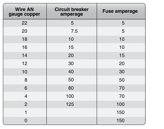
Because the magneto system is self-powered and does not rely on aircraft battery power for spark generation, conventional circuit breakers or fuses in the aircraft's electrical bus do not protect the magneto firing circuits themselves. However, there are electrical components in the ignition system that do draw aircraft power and therefore require protection:
- Starter motor circuit: The starter is a high-current device, typically protected by a heavy-duty circuit breaker or a fusible link rather than a standard circuit breaker, due to the very high inrush current during engine cranking.
- Starter contactor (relay) coil circuit: The small control circuit that energizes the starter contactor is often protected by a circuit breaker on the instrument panel, commonly labeled START or STARTER.
- Ignition switch wiring harness: The cockpit wiring—from the switch to the P-leads—is relatively low-current signal wiring (the P-lead just needs to pull the magneto primary circuit to ground). This wiring is not typically protected by a conventional circuit breaker because interrupting it with a breaker could leave the magneto un-grounded (hot), a more dangerous failure than a shorted wire.
- Impulse coupling and shower-of-sparks systems: Some aircraft use a shower-of-sparks induction vibrator system to assist starting; this circuit does draw battery power and is protected by a circuit breaker, typically labeled IGN or IGNITION VIBRATOR.
The deliberate absence of a circuit breaker in series with the P-lead circuit is itself a design decision: placing a breaker there would mean that a tripped breaker grounds nothing, leaving the magneto hot. The wiring is instead designed to be robust, using shielded cable to prevent radio frequency interference and routed to avoid chafing or damage.
Why It Matters: Maintenance Safety and Airworthiness
AMTs must perform periodic magneto-to-engine timing checks, internal magneto inspections, and breaker point or electronic module replacements at intervals specified in the engine manufacturer's maintenance manual. Every one of these tasks requires the technician to handle the magneto's primary circuit. An untested or assumed-good P-lead connection can cause a prop strike injury that is fatal.
Additionally, improper ignition switch wiring—such as routing a P-lead in a way that could chafe through insulation and contact an airframe ground unintentionally—could cause an in-flight magneto failure with no warning. Inspecting P-lead condition, shielding integrity, and secure connections at the magneto and the switch is a critical part of any engine inspection.
Key Numbers and Rules
- Most aircraft magneto checks call for an RPM drop no greater than 125 RPM on a single magneto, with no more than a 50 RPM differential between left and right (always verify against the specific POH).
- Zero RPM drop on a single magneto position during the mag check is an indication of a failed P-lead—the magneto that should be grounded in that position is not being grounded.
- P-leads use shielded wire; the shield is grounded at one end (typically at the magneto) to reduce radio frequency interference.
- The magneto primary circuit operates at low voltage (battery voltage equivalent internally); the secondary produces 15,000–20,000+ volts to fire spark plugs.
- Under 14 CFR Part 91.409 and applicable maintenance manual requirements, magneto inspection and timing verification are required at each annual inspection.
- Before manually rotating any propeller, confirm: switch to OFF, throttle closed, mixture idle cutoff, and verify P-lead integrity—never assume the switch alone makes the engine safe.
Common Test Traps
- Thinking the switch supplies power to the magnetos: It does not. The ignition switch grounds the magnetos to disable them. An open switch (in OFF) grounds both P-leads—it does not cut off power to anything.
- Confusing switch position names with which magneto is grounded: The LEFT position means the right magneto is grounded (disabled) and the LEFT magneto fires. Students frequently reverse this.
- Assuming a zero RPM drop means a good magneto: A zero drop during the magneto check usually indicates the P-lead is broken or disconnected—the magneto that should be grounded is hot at all switch positions, so switching to that position changes nothing. This is an airworthiness defect, not a sign of an exceptionally smooth magneto.
- Believing turning the ignition OFF makes a prop safe to pull through: If the P-lead is broken, the switch position is irrelevant. Always test P-lead continuity and treat the prop as live unless the ignition leads are disconnected at the spark plugs or magnetos.
- Confusing the starter circuit breaker with magneto circuit protection: The starter contactor coil circuit has a breaker; the P-lead firing circuit does not—intentionally. Adding a breaker in series with the P-lead would create a fail-hot (magneto live) failure mode.