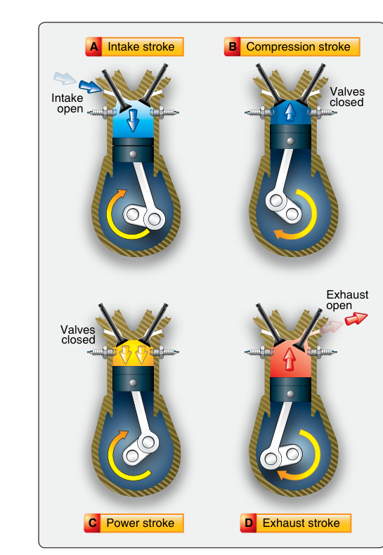
Every piston-driven aircraft engine—from the humble Lycoming O-235 in a trainer to a turbocharged Continental TSIO-550 in a high-performance single—operates on the same fundamental thermodynamic sequence described by the Otto cycle. Named after Nikolaus Otto, who patented the four-stroke internal combustion engine in 1876, this cycle converts the chemical energy stored in aviation gasoline into the rotational mechanical energy that ultimately spins the propeller. For an Aviation Maintenance Technician (AMT) working on powerplant systems, understanding exactly what happens during each stroke—and why the design choices that support each stroke matter—is essential for diagnosing problems, performing inspections, and passing the FAA Powerplant knowledge test.
The term four-stroke refers to the fact that the piston must travel four times inside the cylinder (two complete crankshaft revolutions) to complete one full thermodynamic cycle. Each downward or upward piston travel is one stroke. The four strokes, in order, are: intake, compression, power, and exhaust. The Otto cycle is a constant-volume combustion cycle, meaning the heat addition from burning fuel–air mixture occurs at essentially constant cylinder volume (near top dead center), which distinguishes it from the diesel or Brayton cycles used in other engine types.
The Four Strokes in Detail
Stroke 1: Intake
The cycle begins with the piston at or near top dead center (TDC)—the uppermost position in the cylinder—and both valves momentarily closed. As the crankshaft rotates and the piston begins moving downward toward bottom dead center (BDC), the intake valve opens. This downward movement increases cylinder volume, reducing pressure below atmospheric and creating a pressure differential that draws the fuel–air mixture (from the carburetor or fuel-injection system) through the intake port and into the cylinder. By the time the piston reaches BDC, the cylinder is filled with a combustible charge. The intake valve then closes, trapping the charge.
In practice, the intake valve opens a few degrees of crankshaft rotation before TDC (called intake valve lead) and closes a few degrees after BDC (intake valve lag). This overlap and lag take advantage of the inertia of the incoming charge to pack a denser mixture into the cylinder, improving volumetric efficiency. This is why valve timing specifications are critical during engine overhaul.
Stroke 2: Compression
With both intake and exhaust valves closed and the fuel–air mixture trapped, the piston travels back upward from BDC toward TDC. The mixture is compressed into a much smaller volume. The ratio of the total cylinder volume (piston at BDC) to the clearance volume (piston at TDC) is the compression ratio. Most normally aspirated aircraft engines have compression ratios in the range of approximately 7:1 to 9:1. Turbocharged engines may use slightly lower mechanical compression ratios because the induction system is already delivering pressurized air.
Compressing the mixture does two important things: it raises both the temperature and the pressure of the charge, which dramatically increases the energy released during combustion and improves thermal efficiency. It also makes the mixture more susceptible to detonation—uncontrolled, explosive ignition rather than smooth flame propagation—which is why aviation gasoline octane ratings and the compression ratio must be carefully matched. Using a fuel with too low an octane rating in a high-compression engine is a leading cause of detonation damage.
Stroke 3: Power
Near the end of the compression stroke, before the piston reaches TDC, the spark plugs fire. Aircraft engines use dual ignition—two magnetos, each firing one of two spark plugs per cylinder—both for redundancy and because two flame fronts burn the charge more completely and quickly. The ignition event is timed to occur a specified number of degrees of crankshaft rotation before TDC, known as ignition timing or spark advance. This lead time allows the flame to fully develop so that peak cylinder pressure occurs slightly after TDC, pushing the piston downward with maximum force at the most mechanically advantageous moment.
As the burning gases expand, they exert tremendous pressure on the piston crown, forcing it downward toward BDC. This is the only stroke that produces work output; the other three strokes consume energy. The expanding gases perform work on the piston, which is converted via the connecting rod into torque on the crankshaft. Peak cylinder pressures in a normally aspirated aircraft engine can reach 1,000 psi or more during the power stroke. Both valves remain closed throughout this stroke.
Toward the end of the power stroke, as the piston approaches BDC, the exhaust valve begins to open slightly before BDC (exhaust valve lead). This early opening allows the high-pressure burned gases to begin escaping, taking advantage of the remaining pressure differential to start scavenging the cylinder before the piston begins its upward exhaust stroke.
Stroke 4: Exhaust
With the exhaust valve open and the intake valve still closed, the piston travels back up from BDC toward TDC, pushing the spent combustion gases out through the exhaust port and into the exhaust system. Effective scavenging of burned gases is critical: any residual exhaust gas left in the cylinder dilutes the fresh incoming charge on the next intake stroke, reducing power output. The exhaust valve closes near TDC, and the cycle begins again immediately with the next intake stroke.
The coordinated opening and closing of valves—intake valve opens before TDC on the exhaust-to-intake transition, and both valves are briefly open simultaneously in a period called valve overlap—is carefully engineered to maximize scavenging and charge filling. The camshaft, driven at exactly half crankshaft speed (one cam revolution per two crank revolutions), controls this timing mechanically through the valve train.
Why This Matters for the AMT
Understanding the Otto cycle is not merely academic for the powerplant technician. Virtually every reciprocating engine discrepancy can be traced back to a failure in one or more strokes. A leaking intake valve on compression causes a compression check failure. Incorrect ignition timing affects the power stroke and leads to overheating or detonation. Sticking exhaust valves compromise scavenging and can cause burning of valve faces. Carbon buildup on piston crowns changes the effective compression ratio. The cycle is also the framework for understanding why pre-ignition, detonation, and backfiring occur, and what mechanical or operational conditions trigger them.
During a differential compression check—a standard maintenance procedure—the technician is directly evaluating the integrity of the compression stroke: whether the intake valve, exhaust valve, piston rings, and cylinder walls can adequately seal the cylinder at TDC. FAA standards generally allow a serviceable cylinder to hold a leakage of no more than 25% from the applied test pressure (commonly 80 psi applied, with leakage below 20 psi loss considered acceptable, though manufacturers' limits govern).
Key Numbers and Rules
- Four strokes, two crankshaft revolutions: One complete Otto cycle = two full 360° crankshaft rotations = four piston strokes.
- Compression ratios: Normally aspirated aircraft engines typically 7:1 to 9:1; turbocharged engines often slightly lower mechanically.
- Valve overlap: Both intake and exhaust valves are briefly open simultaneously near TDC between the exhaust and intake strokes to improve scavenging and charge filling.
- Camshaft speed: The camshaft rotates at exactly one-half crankshaft speed so that each valve opens once per complete Otto cycle (every two crank revolutions).
- Dual ignition: Two spark plugs per cylinder, fired by two independent magnetos, are required by 14 CFR 33.37 (ignition system requirements for aircraft engines) and are integral to efficient combustion during the power stroke.
- Only one power stroke per cycle: Of the four strokes, only the power stroke generates work; the other three strokes consume energy stored in the flywheel effect of the rotating crankshaft assembly.
- Differential compression test: Evaluates sealing during the compression stroke; manufacturer limits govern acceptability, but a common rule of thumb is a maximum of 25% leakage from test pressure.
Memory Aid
A widely used mnemonic for the four strokes of the Otto cycle is "Suck, Squeeze, Bang, Blow"—informal but effective:
- Suck — Intake stroke: the piston sucks the fuel–air mixture into the cylinder.
- Squeeze — Compression stroke: the piston squeezes (compresses) the mixture.
- Bang — Power stroke: the spark ignites the mixture, and expanding gases bang the piston down.
- Blow — Exhaust stroke: the piston blows the spent gases out of the cylinder.
While informal, this sequence appears in AMT training materials and is a reliable way to keep the correct stroke order locked in memory under exam pressure.
Common Test Traps
- Confusing "four-stroke" with "four-cycle": These terms describe the same engine; each complete thermodynamic cycle requires four piston strokes and two crankshaft revolutions. Do not confuse with a two-stroke engine, which completes a cycle in one crank revolution.
- Camshaft speed error: A frequent question asks at what speed the camshaft turns relative to the crankshaft. The answer is one-half crankshaft speed, not the same speed. Confusing this leads to incorrect valve timing assumptions.
- The power stroke as the only work-producing stroke: Test questions may ask which strokes produce or consume energy. Only the power stroke produces work; intake, compression, and exhaust all consume energy from the crankshaft's rotational inertia.
- Ignition timing before TDC: Students sometimes assume spark must occur exactly at TDC. In fact, spark occurs before TDC (spark advance) to allow the flame front to develop so peak pressure coincides with the optimal piston position just after TDC.
- Valve overlap confusion: Valve overlap (both valves briefly open simultaneously) occurs near TDC between the exhaust and intake strokes—not during combustion. Confusing when overlap occurs leads to errors on questions about scavenging and volumetric efficiency.