Every aircraft is a complex network of metal structures, wires, avionics boxes, fuel lines, and rotating machinery. Making all of these components work together safely requires more than just connecting the right wires — it demands a disciplined approach to bonding and grounding. These two closely related but distinct practices are foundational to aircraft electrical system design, and they appear consistently on the FAA Aviation Maintenance Technician (AMT) General knowledge test. Understanding why bonding and grounding matter, how they are accomplished, and what can go wrong when they are neglected is essential knowledge for any certificated technician.
At first glance, bonding and grounding can seem interchangeable, but the FAA draws a clear distinction. Bonding is the process of electrically connecting two or more conductive components together so that they share the same electrical potential — no voltage difference exists between them. Grounding is a specific form of bonding in which a component is connected to the aircraft's common ground reference, which on most aircraft is the metallic airframe structure itself. Think of bonding as building bridges between islands and grounding as connecting those islands to the mainland.
Why Bonding and Grounding Are Necessary
Aircraft operate in an environment that is electrically hostile in several ways. Static electricity builds up naturally as the aircraft moves through the air, as fuel flows through lines and into tanks, and as rotating engine and propeller components spin at high speed. Without proper bonding and grounding, these static charges accumulate on isolated metal components and eventually discharge — sometimes as a visible spark. In the vicinity of aviation fuel vapors, a single spark can trigger a fire or explosion. Proper bonding prevents isolated components from developing differing electrical potentials, so no charge can accumulate to dangerous levels.
Beyond fire prevention, bonding and grounding serve several other critical purposes. They provide a low-resistance return path for electrical fault currents, allowing fuses and circuit breakers to detect and interrupt short circuits quickly. They suppress electromagnetic interference (EMI) and radio-frequency interference (RFI) generated by ignition systems, electric motors, and avionics — interference that can corrupt navigation signals or garble communications. They also provide a defined path for lightning-strike energy to flow through the airframe without arcing across fuel systems or sensitive electronics.
How Bonding Works
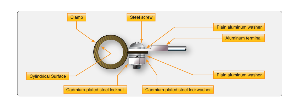
A bonding connection is made using a bonding jumper — typically a short, flexible braid of tinned copper wire or a flat copper strap. The braid design is preferred over solid wire because it is more flexible, resists vibration-induced fatigue fractures, and provides a larger surface area for current flow. The jumper connects two conductive surfaces together, usually through drilled holes and hardware specifically intended for the purpose.
The quality of a bonding connection depends heavily on surface preparation. Anodized aluminum, paint, corrosion-inhibiting coatings, and oxide layers are all electrical insulators — they can make a connection look solid while actually creating high resistance. Proper bonding procedure requires removing any non-conductive coating at the contact points, making bare metal-to-metal contact, installing the bonding jumper with the correct hardware (including serrated washers or star washers to bite through minor surface oxidation), and then protecting the exposed metal with an appropriate corrosion-preventive finish after the connection is made.
The FAA specifies maximum allowable resistance values for bonding connections. According to FAA guidance, the resistance of a bonding connection for general structure bonding should not exceed 0.003 ohms (3 milliohms). Fuel system bonding is especially critical: bonding connections in fuel systems — including fuel caps, fuel valves, and fuel tank attachment hardware — must typically measure 1 ohm or less, though specific aircraft maintenance manuals may call for even tighter tolerances. Always consult the applicable aircraft maintenance manual (AMM) or manufacturer data for the exact specifications for a given installation.
How Grounding Works
On most single-engine and many multi-engine aircraft, the airframe serves as the common ground, allowing the negative terminal of the battery and the ground leads of all electrical components to connect to the structure rather than requiring a dedicated return wire for every circuit. This is called a single-wire electrical system. The airframe completes the circuit, carrying return current back to the battery. This design saves significant weight — eliminating hundreds of feet of return wire — but it places a high premium on maintaining excellent grounding connections throughout the structure.
In a single-wire system, a corroded or loose ground strap between the engine and the airframe can cause all manner of strange electrical behavior: generators or alternators that won't charge, instruments that read incorrectly, avionics that malfunction, and starter motors that turn sluggishly. A poor engine ground is one of the most common electrical faults found during aircraft maintenance, and it is often overlooked because the high-current wiring appears intact.
Some aircraft — particularly those with composite or fiberglass structures that don't conduct electricity — use a two-wire system, in which both the positive and negative conductors must be run to every component, since the structure cannot serve as a return path. In these aircraft, bonding is used to control static and provide lightning protection, but ground return current must travel through dedicated wires.
Static Bonding and Fuel Handling
During ground fueling operations, static electricity poses a particular hazard. Fuel flowing through a nozzle and into a tank generates triboelectric charge — friction between fuel molecules and the nozzle or hose walls separates electrical charges. If the fuel truck, the fuel nozzle, and the aircraft are at different potentials, a spark can jump when the nozzle approaches the aircraft filler port. The standard mitigation is static bonding: attaching a bonding wire between the fuel truck and the aircraft before the fuel cap is opened, equalizing the potential between the two before any fuel or fuel vapor is exposed. Many airports also require the fueling equipment to be grounded to earth ground as an additional precaution.
Static Discharge Wicks
In flight, precipitation static — caused by the aircraft flying through rain, snow, or dust — builds charge on the airframe faster than it can bleed off naturally. Without a means of controlled discharge, this charge reaches levels that cause severe static interference on communications and navigation receivers. Static discharge wicks (also called static dischargers or static wicks) are installed at the trailing edges of control surfaces, wingtips, and tail surfaces to bleed off static charge gradually and at a low current level. They work by creating a region of high electric field at their pointed tips, ionizing the surrounding air and allowing charge to flow off harmlessly without producing broadband radio interference. Damaged or missing static wicks should be replaced promptly, as their absence is immediately apparent in the cockpit as increased radio static in precipitation.
Key Numbers and Rules
- Bonding resistance limit (general structure): must not exceed 0.003 ohms (3 milliohms) per FAA guidance.
- Fuel system bonding: resistance must typically be 1 ohm or less; verify with the specific AMM.
- Bonding jumpers: should be as short as practicable to minimize resistance and inductance.
- Surface prep is mandatory: all non-conductive coatings must be removed at bonding contact points before making the connection.
- Corrosion protection: exposed bare metal at bonding points must be reprotected with an approved corrosion inhibitor after installation.
- Static wicks: typically located at trailing edges of control surfaces; should be inspected for damage at each periodic inspection.
- Single-wire vs. two-wire systems: composite aircraft require two-wire return because the structure is non-conductive.
Common Test Traps
- Confusing bonding with grounding: Bonding equalizes potential between any two conductive components; grounding specifically connects a component to the aircraft's common ground reference. All grounding is bonding, but not all bonding is grounding.
- Resistance value mix-ups: Students frequently confuse the general bonding resistance limit (0.003 ohms) with other resistance specifications. Remember: 3 milliohms is extremely low — a good bonding connection approaches a short circuit in terms of resistance.
- Ignoring surface preparation: A test question may describe a bonding jumper installed over paint or anodizing. This is incorrect procedure. The connection may look mechanically solid but will have unacceptably high resistance.
- Misidentifying the purpose of static wicks: Static wicks do not prevent static from building up — they allow it to bleed off gradually and continuously in a controlled manner that minimizes radio interference. They are not lightning rods.
- Forgetting re-protection after bonding: Leaving bare metal exposed after bonding is an invitation for corrosion, particularly in dissimilar-metal situations. Approved corrosion inhibitor must be applied after the connection is complete.