Before an aircraft engine can run on its own, it must first be spun fast enough for combustion to sustain itself. That spinning is the job of the starter — a device that converts stored energy into mechanical rotation, cranks the engine to sufficient speed, then disengages cleanly so the drivetrain is not damaged once the engine fires. For AMT powerplant candidates, a thorough understanding of starter types, engagement mechanisms, operating limits, and common failure modes is not only tested directly on the FAA knowledge exam but is also foundational to safe maintenance practice on the ramp.
Aircraft starters span a wide range of designs because the engines they serve vary so dramatically — from small reciprocating trainers to large turbine powerplants. Each design represents an engineering trade-off among weight, reliability, starting torque, and energy source. This article covers the major categories recognized in FAA maintenance handbooks, explains how each works mechanically and electrically, and highlights the details most likely to appear on the AMT Powerplant written test.
Direct-Cranking Electric Starters
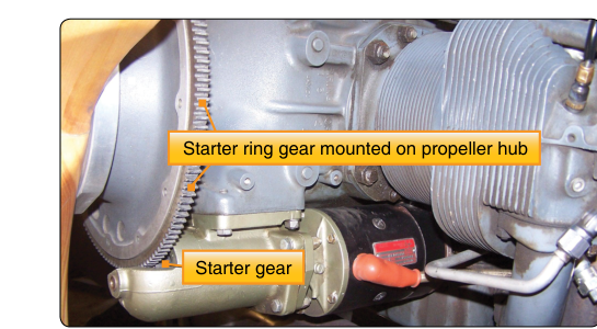
The most common starter found on light reciprocating aircraft is the direct-cranking electric starter. It is essentially a high-torque DC series-wound electric motor connected through a drive mechanism to the engine crankshaft. Series-wound motors are used because they produce maximum torque at zero speed — exactly what is needed to break the engine's static inertia and begin rotation.
When the pilot or technician engages the start switch, battery voltage (typically 12 V or 28 V) is applied to a starter solenoid (sometimes called the starter relay). The solenoid serves two purposes: it carries the very high current — often several hundred amperes — without routing that current through lightweight cockpit wiring, and it provides a discrete, electrically controlled switch. When energized, the solenoid closes its heavy-gauge contacts, connecting the battery directly to the motor.
Inside the starter, the motor armature spins rapidly and drives a Bendix drive — the classic engagement mechanism on most piston-engine starters. The Bendix drive uses an inertia principle: the pinion gear sits on a helically threaded shaft. When the motor armature accelerates, the inertia of the pinion gear causes it to lag behind and therefore thread itself outward along the helix until its teeth mesh with the ring gear on the engine flywheel. Once the engine fires and its speed exceeds starter speed, the now-faster ring gear spins the pinion even faster, causing it to thread back in the opposite direction and disengage automatically. This overrunning action protects the starter motor from being driven at destructive speeds by the running engine.
Some aircraft use a starter-generator combination unit, particularly in turbine-powered aircraft where weight savings are critical. The same machine functions as a starter during engine start and then, once the engine reaches a certain speed, is switched electronically to operate as a generator supplying aircraft electrical power. This eliminates a separate generator and saves significant weight.
Pre-Engaged (Solenoid-Shift) Starters
A variation common on larger reciprocating engines is the pre-engaged starter, also called a solenoid-shift or positive-engagement starter. Rather than relying on pinion inertia to achieve mesh, this design uses the solenoid plunger mechanically linked to the drive pinion. When the start switch is closed, the solenoid first physically shifts the pinion into mesh with the ring gear, and only after mesh is confirmed does the solenoid close the main motor contacts to apply power. This sequence prevents the harsh clashing of gear teeth that can occur if a high-speed motor were energized before mesh. Pre-engaged starters tend to be more reliable on engines with heavier flywheels and are favored where positive, repeatable engagement is required.
Air and Pneumatic Starters
Many turbine aircraft — particularly transport-category jets and turboprops — use pneumatic (air turbine) starters. In these systems, high-pressure air is directed through a turbine wheel inside the starter, causing it to spin at very high speed. A reduction gearbox steps the speed down and multiplies torque to drive the engine's accessory gearbox (AGB), which in turn rotates the engine's compressor and turbine assembly.
The air supply for pneumatic starters can come from several sources: a ground-based high-pressure air cart, the aircraft's auxiliary power unit (APU), or bleed air from an already-running engine on a multi-engine aircraft (cross-bleed start). The starter contains an automatic disconnect mechanism — typically a centrifugal or torque-sensitive clutch — that disengages the starter from the engine once the engine reaches self-sustaining speed, preventing the starter turbine from overspeeding.
A critical maintenance and operational concern with pneumatic starters is the start duty cycle. Turbine starter manufacturers specify maximum engagement times (often 30–60 seconds) and mandatory cooling periods between successive start attempts. Exceeding these limits can overheat internal components and cause premature failure. AMT candidates must know that this information is found in the aircraft and engine manufacturer's maintenance manuals and must be strictly followed.
Combustion (Cartridge/Shotgun) Starters
Military and some specialized aircraft historically used combustion starters, sometimes called cartridge or shotgun starters. A pyrotechnic cartridge is ignited, and the expanding gases drive a turbine or piston mechanism that rotates the engine. These systems provide an entirely self-contained start capability with no dependency on electrical power or ground equipment, which is operationally valuable in remote or combat environments. They are not common in civilian aviation today but appear in FAA study materials because understanding the breadth of starter types is examined.
Engagement Mechanisms in Detail
The Bendix Drive
The Bendix drive relies on the difference in rotational inertia between the armature and the pinion. The helical spline converts this inertia difference into linear motion along the shaft axis, pushing the pinion into mesh. An anti-drift spring holds the pinion retracted when the starter is at rest so it cannot accidentally contact the ring gear. One common failure mode is a stuck Bendix, where the pinion remains engaged after the engine starts. If this occurs, the running engine will spin the starter motor at far beyond its rated speed, potentially destroying the armature windings or causing a fire. The technician's first clue is often a high-pitched whine from the starter after engine start.
Overrunning Clutches
Some starters use a roller-type overrunning clutch (also called a sprag clutch) instead of a Bendix drive. Rollers or sprags are wedged between inner and outer races when torque is applied in the driving direction but cam outward and allow free rotation when the outer race (driven by the engine) exceeds the inner race speed. This design is especially common in starter-generators and in starters for geared engines where smooth, positive engagement is required without the impact loading of an inertia drive.
Why Starter Knowledge Matters for Safety
Improper starter operation or undetected starter faults are genuine hazards. A starter that fails to disengage after engine start will be destroyed within seconds and may cause an electrical fire. A starter that drags — drawing excessive current without turning the engine — will quickly deplete the battery and may overheat wiring. Ground technicians must verify that starter limits are not exceeded: most manufacturers specify a maximum of three start attempts before a mandatory cool-down period, and the AMT is responsible for logging and tracking starter engagement times during maintenance runs.
On turbine engines, a hung start (engine lights off but fails to accelerate to idle) or a hot start (exhaust gas temperature exceeds limits during start) are often starter-related; if the starter disengages too early, the engine may not have sufficient rotational energy to accelerate on its own. Understanding the starter's role in the start sequence — and how to recognize when it is not performing correctly — is directly tied to engine health and crew safety.
Key Numbers and Rules
- Series-wound DC motor: Standard for direct-cranking electric starters; provides maximum torque at stall speed.
- Starter solenoid current: Hundreds of amperes; always use proper gauge cables and verify terminal torque to prevent resistance heating.
- Pneumatic starter engagement limits: Typically 30–60 seconds maximum per start attempt; always consult the specific maintenance manual.
- Duty cycle cool-down: Most manufacturers require a 1–5 minute cool-down between start attempts; three attempts is a common maximum before an extended cool-down period.
- Self-sustaining speed (turbine): The starter must remain engaged until the engine reaches the speed at which combustion can maintain acceleration on its own; this varies by engine but is typically 40–60% N1 for large turbofans.
- Starter-generator transition: Occurs automatically at a defined engine speed; the control circuit opens the start relay and reconfigures the machine as a generator.
Common Test Traps
- Bendix vs. pre-engaged confusion: The Bendix relies on pinion inertia for mesh; the pre-engaged starter mechanically shifts the pinion before applying motor power. Mixing these up is a frequent error on the knowledge test.
- Overrunning direction: Students sometimes think the overrunning clutch disengages the starter when the starter is spinning fast. In reality, it disengages when the engine (the driven side) outpaces the starter (the driving side) — the direction of relative motion is what matters.
- Starter-generator vs. separate units: A starter-generator performs both functions in one housing; it does not work as both simultaneously. It starts first, then switches to generate. Some questions try to imply both functions are active at once.
- Duty cycle is not optional: Questions may present a scenario where a technician exceeds start attempt limits to save time. The correct answer always requires adherence to manufacturer limits — no exceptions.
- Air source for pneumatic starters: The question may ask what provides air for a cross-bleed start. The answer is bleed air from an operating engine — not the APU (which is one source, but not the definition of a cross-bleed start) and not ram air.