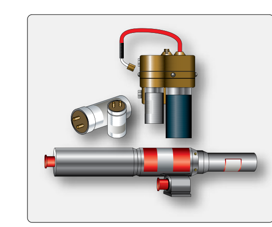
Starting a turbine engine is far more demanding than cranking a piston powerplant. Jet fuel must be atomized, mixed with air, and ignited under conditions that vary from sea-level heat to sub-zero high-altitude cold. To accomplish this reliably, turbine engines use a specialized ignition system built around two key components: the ignition exciter unit, which generates the enormous electrical energy needed to fire an igniter plug, and the igniter plug itself — with glow plugs used mainly in some auxiliary power units (APUs) and small gas turbines/turboshafts for starting. Understanding both devices, how they work together, and when each type is used is essential knowledge for any Aviation Maintenance Technician (AMT) working on powerplants.
Unlike a piston engine's continuous-spark magneto system, most turbine ignition systems operate only during engine start and, in some cases, during specific flight conditions such as flight through heavy precipitation or when an in-flight relight may be needed. This intermittent duty cycle means the system can be designed to deliver energy levels that would destroy a conventional spark plug if applied continuously — and indeed, turbine igniter plugs receive energy levels many times greater than those used in reciprocating engines.
How Ignition Exciter Units Work
The ignition exciter unit is the electrical heart of a turbine ignition system. Its job is to take the relatively low voltage available from the aircraft's electrical bus and transform it into a very high-energy discharge capable of jumping the gap inside an igniter plug through a fuel-air mixture that is difficult to ignite. The output energy of a typical exciter is measured in joules, and values commonly range from about 1 joule to 4 joules, with some high-energy or low-tension systems reaching up to about 20 joules per spark, depending on the engine application. This is orders of magnitude above a piston engine's ignition output.
Inside the exciter, the incoming voltage is first passed through a transformer and rectifier circuit (in AC input systems) or a DC-to-DC converter (in DC input systems) to raise the voltage to a high intermediate level. This elevated voltage is then used to charge a storage capacitor — a device that accumulates electrical charge over a brief period, typically a fraction of a second. Once the capacitor reaches the designed trigger voltage, a discharge gap or triggering device releases all stored energy in a single extremely brief, high-intensity pulse. This pulse is delivered through a shielded, high-tension ignition lead to the igniter plug.
Two broad categories of exciters exist. A low-tension exciter charges its capacitor to a relatively modest voltage and relies on a semiconductor or arc-gap trigger to release the charge. A high-tension exciter raises voltage high enough that the discharge arc fires spontaneously across the internal gap. Most modern turbine engines use high-tension or medium-tension systems because the high energy output ensures reliable ignition even in adverse conditions. Some engines use dual exciter units — one for each igniter plug — providing redundancy so that if one exciter or plug fails, ignition can still be achieved.
Ignition Leads
The high-tension lead connecting the exciter to the igniter plug is a critical component. These leads are heavily shielded coaxial cables designed to contain the intense electromagnetic pulse that accompanies each discharge. They must be routed away from fuel lines and must be inspected carefully for chafing, cracking of the outer insulation, and security of the coupling nuts at each end. A degraded lead can cause misfiring, energy loss, or electrical interference with aircraft avionics.
Igniter Plugs in Turbine Engines
The igniter plug in a turbine engine is fundamentally different from a piston engine's spark plug. Rather than creating a small, hot spark to ignite a compressed fuel-air charge in a sealed cylinder, the turbine igniter must project a high-energy, plasma-like discharge into the open combustion liner where fuel and air are flowing continuously. Two main types of igniter plugs are used:
- Annular gap (shunted) igniters — These are the most common type. The electrode is recessed within a ceramic insulator, and the high-energy discharge projects outward into the combustion zone. This design tends to resist carbon fouling because of the force of each successive discharge, though exact performance characteristics should be verified against manufacturer literature.
- Constrained gap igniters — The electrode gap is constrained or shielded so that the discharge is forced along a surface, producing an intense plasma jet. These are often used in applications requiring even higher ignition reliability.
Igniter plugs are typically installed in the lower portion of each combustion can or at specific points in an annular combustion chamber, positioned where the fuel-air ratio and flow characteristics are optimal for initial flame propagation. Most turbine engines use two igniter plugs per engine, positioned 180 degrees apart or at engineering-determined locations. Once the flame is established, it propagates throughout the combustion chamber without further assistance from the ignition system.
Glow Plugs in Turbine and Turboshaft Applications
Glow plugs represent an alternative starting approach used mainly in some auxiliary power units (APUs) and small gas turbine or turboshaft engines. Rather than producing a high-energy spark, a glow plug contains a resistive heating element that glows at very high temperature when current is applied, providing a continuous hot surface that ignites fuel as it contacts or passes near the element. This is conceptually similar to a glow plug in a diesel engine, but designed for the specific fuel flow and pressure characteristics of a small gas turbine.
The advantage of a glow plug system is simplicity and lower electrical peak-power demand — the exciter and high-tension discharge circuit are eliminated. The heating element draws sustained current and reaches ignition temperature within a few seconds of power application.
However, glow plugs have limitations in larger turbine engines: they are less effective at altitude where lower air density and pressure make sustained surface ignition less reliable. High-energy spark ignition, therefore, dominates in aircraft turbofans and turbojets, while glow plugs remain more limited to APUs and small ground-based or low-altitude turboshaft applications.
Why These Systems Matter to the AMT
Turbine ignition system failures do not always announce themselves dramatically. A faulty exciter may produce inconsistent spark output, leading to a hot start (if fuel is admitted but ignition is delayed) or a hung start (if the engine stabilizes at a sub-idle RPM and temperatures). Both conditions can cause severe damage to the turbine section in a very short time. An AMT must be able to interpret engine start parameters — specifically the rate of EGT rise and the RPM acceleration rate — to determine whether the ignition system is performing correctly.
Routine maintenance tasks include inspecting igniter plugs for electrode erosion, checking gap dimensions against the manufacturer's specifications, examining the ceramic insulator for cracks or carbon tracking, and testing exciter output with approved test equipment. Igniter plugs have a finite service life measured in operating hours or number of starts, and must be replaced on schedule regardless of apparent condition, because electrode erosion that is invisible to the naked eye can significantly reduce discharge energy.
Key Numbers and Rules
- Exciter output energy typically ranges from approximately 1 to 4 joules per spark in common turbine applications, with some high-energy or low-tension systems reaching up to about 20 joules — always verify the specific value in the applicable maintenance manual.
- Most turbofan and turbojet engines use two igniter plugs per engine, located at prescribed positions in the combustion section.
- Igniter plugs tend to resist carbon fouling due to the force of each high-energy discharge — but exact self-cleaning performance and service claims should be confirmed against manufacturer literature.
- Ignition exciter units should be handled with extreme care even after power is removed — capacitors can retain a lethal charge for a period after shutdown; always follow manufacturer discharge procedures.
- Ignition leads must be bonded and shielded to prevent electromagnetic interference and must be inspected for chafing at every opportunity.
- Glow plug systems are used mainly in APUs and some small gas turbine/turboshaft engines for starting; high-energy spark systems dominate turbofans and turbojets.
- Replacement of igniter plugs is typically scheduled by operating hours or start cycles, as specified in the engine manufacturer's maintenance manual.
Common Test Traps
- Confusing exciter output with piston ignition energy. The FAA knowledge test may present questions implying turbine ignition energy is similar to piston spark energy — it is not. Turbine exciters produce many times more energy, which is why turbine igniter plugs are not interchangeable with piston spark plugs.
- Assuming ignition runs continuously. Students sometimes assume turbine ignition is continuous like magneto-fired piston ignition. In most turbines, ignition is used only for start and selected in-flight conditions. Continuous ignition is a specific, selectable mode, not the norm.
- Overlooking residual capacitor charge hazards. Exam questions on maintenance safety frequently test whether the technician knows that exciter capacitors can hold a dangerous charge after power is removed. Always discharge per the manual before handling.
- Mixing up igniter plug types. Annular gap and constrained gap igniters are not interchangeable. Substituting an incorrect type can result in poor ignition performance or plug damage — always use the part number specified in the maintenance manual.
- Ignoring igniter plug service life intervals. Because turbine igniter plugs tend to resist carbon fouling and may appear serviceable, technicians may be tempted to defer replacement. The test emphasizes that electrode erosion affects discharge energy even when the plug looks intact, and scheduled replacement is mandatory.