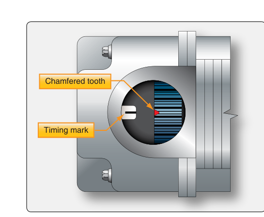
Magneto timing is one of the most consequential maintenance tasks an aviation powerplant technician performs. When spark plugs fire at precisely the right moment relative to piston position, the fuel-air mixture burns efficiently, producing maximum power while protecting engine components from heat and pressure damage. Timing that is even slightly off — too early or too late — can result in loss of power, detonation, engine roughness, or in severe cases, catastrophic engine failure. Understanding both the theory behind magneto timing and the step-by-step procedures for setting it correctly is essential knowledge for the FAA Powerplant mechanic certificate.
There are two distinct but related timing concepts every AMT must master: internal timing, which concerns the relationship of components within the magneto itself, and engine timing (also called external timing or magneto-to-engine timing), which aligns the magneto's output to the correct piston position in the engine's cylinders. Both must be correct for the ignition system to function properly.
How Magneto Ignition Works
A magneto is a self-contained, engine-driven alternating-current generator that produces high-voltage ignition sparks independently of the aircraft's battery or electrical system. Inside the magneto, a rotating permanent magnet assembly spins past stationary pole shoes wound with primary and secondary coils. As the magnet rotates, it generates a changing magnetic flux through the primary coil, inducing a relatively low voltage. Just past the point of maximum flux — at an angular position called the E-gap position — the breaker points (in a conventional magneto) are timed to open, collapsing the primary field extremely rapidly at the moment the rate of flux change is greatest. This rapid collapse induces a very high voltage — commonly cited as up to 20,000 volts or more, though exact figures vary by design — in the secondary winding. That voltage is then distributed through the distributor rotor and harness to the appropriate spark plug.
The E-gap (efficiency gap) is the specific angular position of the rotating magnet, slightly past the point of maximum flux, at which the points are set to open. Opening the points at this angle ensures the rate of change of magnetic flux through the primary coil is at its maximum at the instant of opening, producing the strongest possible primary current and thus the highest possible secondary voltage. If the points open at any other position, the induced secondary voltage is lower and spark intensity suffers. Setting the internal timing of the magneto means ensuring the points open exactly at the E-gap position.
Internal Timing of the Magneto
Internal timing is performed on the magneto itself, either on a test bench or before installation on the engine. The procedure establishes the correct relationship between the rotating magnet and the breaker points (or, in capacitor-discharge magnetos, the triggering mechanism). The steps generally follow this sequence:
- Identify the E-gap position. Using a timing light or continuity tester connected across the breaker points, rotate the magneto drive shaft until the magnet reaches its E-gap position. Many magnetos have a reference mark on the drive shaft coupling or housing that indicates E-gap. Some manufacturers also provide a small timing window or alignment mark on the magneto body.
- Verify points just open. At the E-gap position, the breaker points should be at the verge of opening — the continuity tester transitions from a closed (continuity) to an open (no continuity) circuit at exactly this point. A timing light will extinguish at the moment of point opening.
- Adjust the breaker point gap. Point gap affects cam dwell and indirectly influences when the points open relative to the cam's rotation. Manufacturers specify the gap, commonly somewhere in the range of about 0.008 to 0.018 inches depending on the magneto model, though the specific value must always be confirmed in the applicable maintenance manual. A feeler gauge is used to set this gap with the rubbing block on the high point of the cam lobe.
- Verify and lock. After setting the gap, recheck that points open at the correct E-gap position. Tighten the point assembly securing hardware and recheck timing once more, since tightening can shift the setting slightly.
Engine Timing — Magneto-to-Engine Timing
Once internal timing is confirmed correct, the magneto must be mounted to the engine so that the spark fires at the correct crankshaft angle before the piston reaches top dead center (TDC) on the compression stroke. This advance before TDC is expressed in degrees of crankshaft rotation and is specified by the engine manufacturer. Many horizontally opposed aircraft engines are timed somewhere in the low-to-mid 20s BTDC, though the exact value is engine-specific and must always be confirmed in the engine's type certificate data sheet or maintenance manual.
Why fire before TDC? Combustion of the fuel-air mixture is not instantaneous — it takes a measurable fraction of a second for the flame front to fully develop and propagate across the cylinder. By initiating the spark early, the designer ensures that peak combustion pressure is reached just after TDC, when the piston is in the optimal position to convert that pressure into crankshaft torque. If the spark fires too late (over-retarded), peak pressure occurs when the piston is already moving rapidly downward, wasting much of the combustion energy. If the spark fires too early (over-advanced), peak pressure pushes against a piston still moving upward toward TDC — this creates severe mechanical stress and can cause detonation.
Finding Top Dead Center
The first step in engine timing is accurately locating TDC for the number-one cylinder (the reference cylinder, which varies by engine but is typically the front cylinder or the first cylinder to fire in the sequence). A piston position indicator (also called a top dead center indicator or timing plug) is inserted into the spark plug hole of the number-one cylinder. The crankshaft is then rotated by hand until the piston reaches its highest point, which is confirmed by the indicator. Alternatively, a timing disc attached to the propeller flange combined with a pointer fixed to the engine provides a direct degree-of-rotation readout. The disc is zeroed at TDC.
Setting the Timing Advance
With TDC established, the crankshaft is rotated backward (opposite normal direction of rotation) past TDC, then rotated forward in the normal direction until the timing mark on the disc aligns with the pointer at the specified BTDC value — for example, 25° BTDC. The magneto is then installed (or adjusted on its mounting pad) until a continuity tester or timing light indicates the magneto's points are just opening at that exact crankshaft position. On many engines, magneto mounting flanges allow rotation of the magneto body to fine-tune timing; the magneto is secured at the point where the timing light indicates proper break.
Both magnetos are timed in the same way. On a dual-magneto engine, each magneto must be timed to the same specification. A slight difference in timing between left and right magnetos is normal to a small degree, but large differences create noticeable engine roughness during the magneto check. Manufacturer and POH limits vary, but training materials commonly cite a maximum RPM drop of around 150 RPM on either magneto and a maximum differential drop of about 50 RPM between the two magnetos during the engine runup magneto check, though specific limits are always confirmed in the engine's documentation.
Why Magneto Timing Matters
Correct timing is fundamental to engine airworthiness. Retarded timing reduces power output and increases exhaust gas temperatures, potentially damaging exhaust valves and turbine components on turbocharged engines. Advanced timing risks detonation — uncontrolled explosive combustion that can punch holes in pistons, crack cylinder heads, and destroy bearings in a matter of seconds. In flight, the consequences of severe detonation are often catastrophic and unrecoverable.
From a regulatory standpoint, magneto timing must be set in accordance with the engine manufacturer's approved data, which is part of the engine's type certificate. Any deviation from that data is a potential airworthiness discrepancy. The FAA requires that maintenance performed on certificated aircraft engines conform to the manufacturer's maintenance manual or Instructions for Continued Airworthiness (ICA) under 14 CFR Part 43.
Key Numbers and Rules
- E-gap: The specific angular position of the rotating magnet, slightly past the point of maximum flux, at which the breaker points are timed to open — producing the maximum primary flux change rate at the moment of opening. Exact E-gap degrees vary by magneto model; always reference the applicable maintenance manual.
- Breaker point gap: Commonly in the range of about 0.008 to 0.018 inches depending on the magneto model, but must be confirmed in the manufacturer's data — never assumed.
- Timing advance (typical): Many horizontally opposed piston engines are timed in the low-to-mid 20s BTDC; always confirmed in the engine type certificate data sheet or maintenance manual.
- Maximum RPM drop per magneto: Commonly cited around 150 RPM during runup magneto check (manufacturer/POH limit applies).
- Maximum differential between magnetos: Approximately 50 RPM difference (manufacturer/POH limit applies).
- 14 CFR Part 43: Governs maintenance, preventive maintenance, rebuilding, and alteration; timing adjustments must be logged in the aircraft maintenance records.
- Continuity tester or timing light: The primary tool used to detect point-opening during both internal and external timing procedures.
Common Test Traps
- Confusing internal and external timing: Internal timing sets point opening to E-gap within the magneto itself. External timing aligns that event to the correct crankshaft position on the engine. The FAA knowledge test may describe one and ask about the other — read carefully.
- Assuming a fixed timing value: There is no single universal timing advance in degrees that applies to all engines. Test questions that list a specific degree value require you to know it comes from the engine manufacturer's approved data, not a universal FAA rule.
- Rotating in the wrong direction to set timing: When positioning the crankshaft to the timing point, you must approach the mark from the correct direction of rotation to eliminate backlash errors in gears and couplings. Rotating past and backing up reintroduces error.
- Ignoring point gap after tightening: Tightening the point assembly hardware can shift the breaker point gap slightly. Failing to recheck timing after final tightening is a classic shop error that leads to mis-timed magnetos.
- Treating a high RPM drop as always bad: A high RPM drop on one magneto during runup could indicate retarded timing, fouled plugs, or a failing magneto — the test may ask you to distinguish between these causes. Retarded timing specifically produces a larger-than-normal drop rather than no drop at all.