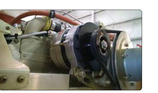
Every aircraft with an engine-mounted electrical power source relies on either a generator or an alternator to keep the battery charged and supply continuous power to avionics, lighting, fuel pumps, and flight instruments. While both devices accomplish the same fundamental goal — converting crankshaft rotation into electrical energy — they do so through distinctly different principles, and each type presents unique maintenance considerations. For AMT powerplant candidates, mastering the construction, operating theory, regulation circuitry, and common failure indicators for both types is not only an FAA knowledge-test requirement but a genuine safety imperative.
This article covers the direct-current (DC) generator used on older piston-engine and turbine aircraft, the alternating-current alternator (often called an AC alternator or, in its rectified form, an alternator with integral rectifier) used on virtually all modern piston aircraft, and the voltage regulation and protection circuits that keep either device operating safely within system limits.
How the DC Generator Works
A DC generator operates on the principle of electromagnetic induction: when a conductor moves through a magnetic field, a voltage is induced in that conductor. In the aircraft generator, the rotating component is called the armature, which consists of many loops of wire wound on an iron core. The armature spins inside a fixed magnetic field produced by field coils (also called field windings) wound around pole pieces in the generator housing. As each armature loop cuts through the magnetic flux, an alternating voltage is naturally induced — but a mechanical device called the commutator reverses the connection of each loop to the output circuit at exactly the right moment, so that the current delivered through the brushes to the external circuit is a pulsating but effectively unidirectional (DC) output.
The brushes are spring-loaded carbon blocks that ride against the commutator segments, carrying current from the rotating armature to the stationary external circuit. Because carbon-on-copper contact involves both friction and electrical arcing, brushes are a primary wear item that must be inspected regularly for length, spring tension, and condition of the commutator surface. A glazed, grooved, or burned commutator is a classic sign of brush or generator problems and calls for undercutting the mica insulation between segments and resurfacing the copper.
Generator output voltage rises with increasing rotational speed, so a voltage regulator is mandatory. The traditional three-unit regulator found on older aircraft contains a voltage regulator (which limits maximum voltage by varying field current), a current limiter (which protects the generator from overload), and a reverse-current cutout relay (which disconnects the generator from the bus when generator voltage falls below battery voltage, preventing the battery from motoring the generator backward). Understanding these three functions is frequently tested on the AMT knowledge exam.
How the Alternator Works
The aircraft alternator solves the brush-wear problem of the DC generator by reversing the arrangement: the field rotates (carried on the rotor) while the output windings (the stator) remain stationary. A small amount of DC field excitation current is still delivered to the rotor through slip rings and brushes, but because field current is much smaller than armature current, brush and slip-ring wear is dramatically reduced.
The rotating field induces a three-phase AC voltage in the stator windings. A rectifier assembly — typically six silicon diodes arranged in a bridge configuration — converts the three-phase AC into smooth DC for the aircraft bus. Because three-phase rectification produces very little ripple, a large filter capacitor is not needed. The diodes also inherently block reverse current, eliminating the need for a separate cutout relay.
A critical advantage of the alternator is that it produces useful output at much lower engine RPM than a comparable generator. Generators generally require substantially higher engine speed before they produce adequate charging output, whereas an alternator typically reaches charging voltage at or near idle. Exact minimum charging speeds vary by installation and are established by the airframe and component manufacturer, not by a fixed FAA figure. This makes alternators especially valuable during low-power operations such as taxi, approach, and engine run-up checks.
Alternator output is regulated by controlling field current. The solid-state voltage regulator senses bus voltage and modulates field current through a transistorized circuit to hold bus voltage steady, at a nominal setpoint of approximately 14 volts on a 14-volt system or approximately 28 volts on a 28-volt system; exact regulation setpoints vary by aircraft and system design.
Voltage Regulation and Protection Circuits
Both generators and alternators require voltage regulation; unregulated output would damage avionics, overcharge the battery, and potentially cause battery electrolyte to boil. Modern solid-state regulators use transistors and zener diodes to sense bus voltage precisely and make continuous, smooth corrections to field current — eliminating the contact chatter and maintenance issues of older vibrating-point regulators.
In addition to the basic regulator, most alternator systems include an over-voltage protection relay (OVR) or crowbar circuit. If a regulator fails and allows voltage to rise above a set threshold (commonly around 16 volts on a 14-volt system), the OVR opens the alternator field circuit — or in some designs, connects a low-resistance shunt across the field — to instantly collapse field current, and an associated relay disconnects the alternator from the bus. This protects sensitive avionics from destructive overvoltage. Once an OVR has tripped, it often requires resetting on the ground and investigation of the regulator before returning to service.
Some installations include a load-meter or ammeter in the cockpit to monitor charging system output. A center-zero ammeter shows whether the battery is charging or discharging; a load-meter (left-zero ammeter) reads total alternator output current. Pilots and technicians should understand which type is installed and what normal indications look like.
Why It Matters
Electrical system failures in flight can range from minor inconvenience to serious emergencies. A failed charging source means the aircraft is operating entirely on battery power — a finite resource whose endurance depends on battery condition, capacity, and electrical load, and can be exhausted quickly under normal operating loads. Technicians must ensure that the charging system is correctly calibrated and that the battery is serviceable so the combination provides adequate backup. Improperly adjusted voltage regulators can silently overcharge or undercharge the battery for hundreds of flight hours, degrading battery capacity and reliability without obvious symptoms until failure occurs.
On turbine aircraft, engine-driven AC generators (often called integrated drive generators, or IDGs) are used, but the fundamental principles of electromagnetic induction, voltage regulation, and protection circuits remain applicable. Powerplant AMTs working on turbine aircraft will encounter constant-speed drives and frequency-wild AC systems that build directly on this foundation.
Key Numbers and Rules
- Regulated bus voltage (14V system): nominal setpoint approximately 14 V DC; overvoltage protection usually trips at approximately 16 V.
- Regulated bus voltage (28V system): nominal setpoint approximately 28 V DC.
- Brush inspection: brushes must be checked for minimum allowable length (consult the generator manufacturer's service data); worn brushes cause arcing and commutator damage.
- Commutator mica undercutting: mica between commutator segments must be undercut to a depth specified by the manufacturer so brushes ride on copper, not mica.
- Three-unit regulator components: voltage regulator, current limiter, and reverse-current cutout relay — all three functions must be understood separately.
- Alternator diode check: a shorted diode will cause AC ripple on the DC bus, which can damage avionics; an open diode reduces output and may cause uneven heating in the stator.
- Alternator low-RPM advantage: alternators begin charging at or near engine idle; generators require higher RPM for adequate output (exact figures vary by installation).
Common Test Traps
- Generator vs. alternator brush current: A common error is assuming alternators have no brushes. They do — but brushes carry only low-level field current through slip rings, not high armature current through a commutator. This distinction explains why alternator brushes last far longer.
- Reverse-current cutout relay vs. OVR: The reverse-current cutout relay protects against the battery driving the generator; the over-voltage relay (or crowbar) protects against excessive generator/alternator output voltage. Students often confuse the direction of protection.
- Three-unit regulator on alternators: The three-unit regulator is associated with DC generators, not alternators. Alternators use a solid-state voltage regulator and rely on diodes for reverse-current blocking. Misidentifying which regulation scheme belongs to which device is a frequent test mistake.
- Ammeter type confusion: A center-zero ammeter indicates charging (+) or discharging (−) of the battery; a left-zero (load) meter reads total alternator load. Confusing the two leads to incorrect interpretation of in-flight charging system status.
- Shorted diode symptoms: A shorted rectifier diode in an alternator does not simply reduce output — it creates an AC ripple on the DC bus. Students sometimes assume a shorted diode would just lower voltage, but the AC contamination is the more operationally dangerous effect.