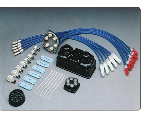
Every time a magneto fires, it produces a burst of high-voltage electricity — often exceeding 20,000 volts — that must travel reliably from the magneto to the correct spark plug at precisely the right moment. The ignition harness is the complete assembly of leads, terminals, and protective coverings that makes this possible. At the same time, those powerful high-frequency electrical pulses are natural sources of radio frequency interference (RFI), which can corrupt communications and navigation avionics. That is why every certificated aircraft ignition harness is also a shielded assembly — a carefully engineered system that contains the electromagnetic energy within the lead itself rather than broadcasting it through the airframe. Understanding how ignition harnesses are built, how shielding works, and what the maintenance standards require is essential knowledge for any Aviation Maintenance Technician (AMT) working on reciprocating engines.
Construction of the Ignition Harness
An ignition harness is not simply a set of wires. Each lead is a precisely layered assembly designed to handle extreme voltage, wide temperature swings, vibration, and the continuous flexing that occurs during engine operation. From the inside out, a typical ignition lead consists of the following layers:
- Center conductor: A stranded or solid conductor — often a carbon-core or resistor-type — that carries the high-voltage impulse. Resistor-type conductors help suppress RFI by adding series resistance that dampens the sharp edges of the voltage pulse.
- Insulation: A thick layer of high-dielectric-strength material, commonly silicone rubber, that prevents the high voltage from arcing to surrounding structure. The insulation must withstand the full open-circuit voltage of the magneto without breakdown.
- Shielding braid: A woven metal braid — typically tinned copper — that surrounds the insulation. This braid is the heart of the RFI suppression system. It is grounded at both ends (at the magneto and at the spark plug) so that any electromagnetic energy radiating outward from the center conductor is intercepted by the braid and conducted safely to ground rather than escaping into the airframe or airspace.
- Outer jacket: A protective covering, again usually silicone or a similar high-temperature material, that shields the braid from abrasion, fuel, oil, and heat.
At each end of the lead, the harness terminates in a precision fitting. At the spark plug end, terminal designs vary by manufacturer — commonly a spring and terminal sleeve or cap/nut assembly, and in some designs a carbon button, seats against the spark plug terminal. At the magneto end, the lead connects to the distributor block or distributor rotor outlet. Both terminations must provide a continuous ground path from the shielding braid to the engine or magneto case — any interruption in this ground path degrades shielding effectiveness immediately.
How Shielding Suppresses Radio Frequency Interference
To understand shielding, think of the ignition lead as a coaxial transmission line — the same principle used in antenna feed lines. The center conductor carries the signal (in this case, the high-voltage pulse), and the outer braid acts as a return path and a Faraday shield. When the braid is properly grounded, it intercepts the electromagnetic energy radiating from the center conductor and provides a low-impedance path that conducts the induced currents safely to ground, containing the field within the lead rather than allowing it to radiate outward. The result is that virtually no electromagnetic energy escapes beyond the outer surface of the lead.
This matters enormously in the cockpit. Without shielding, each magneto firing — which occurs hundreds of times per minute at cruise RPM — would generate a sharp pulse of RFI audible as a buzzing or clicking in the headset that varies with engine speed. More seriously, unshielded ignition systems can disrupt VOR, ADF, and older GPS receivers. The FAA requires shielded ignition systems on all certificated aircraft to protect airborne navigation and communication equipment, and the AIM reinforces the importance of proper shielding maintenance for avionics reliability.
Magneto-to-Harness Interface
The magneto distributor block is the point where the harness connects to the rotating high-voltage distribution system inside the magneto. Distributor blocks are made of a high-dielectric plastic material. The individual lead outlets on the block must be clean and free of carbon tracking — fine carbon paths burned into the surface of the block by repeated arcing. Carbon tracking creates a conductive path that allows high voltage to leak to adjacent outlets or to ground, causing misfires, rough running, and even complete loss of the affected magneto's output on one or more cylinders.
During a magneto inspection, the AMT examines the distributor block carefully for carbon tracking, cracks, or erosion of the outlet bores. A contaminated or cracked distributor block is replaced, not repaired. The lead-to-block connection must also be tight and correctly torqued — a loose connection allows the high voltage to arc at the interface, accelerating carbon tracking and degrading the shielding continuity.
Spark Plug Lead Inspection and Testing
Because ignition leads operate in a hot, vibrating, chemically hostile environment, they are subject to insulation breakdown, conductor fatigue, and braid corrosion over time. The FAA and aircraft manufacturers specify inspection intervals and serviceability limits in the aircraft maintenance manual and the applicable magneto overhaul manual. The primary test tool for ignition lead condition is the ignition harness tester, sometimes called an ignition analyzer.
The harness tester applies a known high DC voltage across the insulation of each lead while measuring leakage current; the exact test voltage varies by tester and manufacturer specification. A good lead shows very high insulation resistance, generally in the megohm range. Most manufacturers specify a minimum insulation resistance that, if not met, requires lead replacement. A lead with degraded insulation will leak current to the shielding braid, reducing the voltage actually available at the spark plug and potentially causing misfires, especially at altitude where lower air density means the spark gap requires a higher voltage to fire reliably.
In addition to the high-voltage insulation test, the AMT performs a visual inspection of the entire harness. Key items include:
- Checking for chafing of the outer jacket against hot exhaust components, engine mounts, or airframe structure.
- Looking for kinks, sharp bends, or areas where the lead has been pinched — these can crack the insulation or break strands in the shielding braid.
- Inspecting all ferrules, clamps, and tie points for security and correct routing away from heat sources.
- Verifying that lead grommets or clamps at firewall penetrations are intact and that no lead is under tension.
Installation Requirements and Routing
Correct routing of ignition leads is not optional — it is a safety requirement. The FAA's Aviation Maintenance Technician Handbook – Powerplant (FAA-H-8083-32) and the applicable engine manufacturer's maintenance manual specify minimum clearances from exhaust stacks, turbocharger components, and other heat sources. Ignition leads exposed to excessive heat will harden and crack, compromising both insulation and shielding. As a general rule, leads should be routed with gentle curves rather than sharp bends, supported at regular intervals to prevent vibration fatigue, and kept clear of moving parts.
Lead length is also significant. Excessively long leads increase the capacitance of the ignition circuit, which can reduce the peak voltage delivered to the plug. Leads that are too short create mechanical stress at the terminations. The correct leads for a given installation are specified by part number in the aircraft or engine type certificate data — substituting incorrect length leads is not an acceptable field repair.
Key Numbers and Rules
- High-voltage range: Modern aircraft magneto systems typically produce 15,000 to 20,000+ volts open-circuit at the lead terminal.
- Insulation resistance minimums: Minimum insulation resistance values vary significantly by manufacturer and lead type; always consult the specific magneto or harness manufacturer's data for the serviceable limit.
- Shielding ground continuity: The resistance from the shielding braid to the engine ground must be essentially zero; measurable resistance indicates a broken or corroded braid or a poor fitting contact.
- Carbon tracking: Any visible carbon track on a distributor block, cap, or lead ferrule is cause for rejection and replacement of the affected part.
- Lead replacement at overhaul: Most manufacturers recommend replacing the entire ignition harness at each magneto overhaul interval rather than reusing old leads, regardless of visual condition.
- Routing clearance: Follow engine manufacturer minimums, as actual clearance requirements vary by aircraft/engine type certificate data — always consult the specific maintenance manual for exact requirements.
Common Test Traps
- Confusing open-circuit voltage with firing voltage: The magneto produces very high open-circuit voltage, but the actual voltage that appears across the spark plug gap depends on the gap setting, electrode condition, and insulation quality of the lead. A degraded lead reduces delivered voltage.
- Assuming a good visual means good insulation: A lead can look perfect externally yet have severely degraded insulation that only shows up under high-voltage testing. Always use the ignition harness tester — visual inspection alone is insufficient.
- Overlooking shielding continuity at the fitting: The most common shielding failure is not a broken braid but a corroded or improperly installed ferrule that fails to make solid contact between the braid and the engine or magneto ground. Check continuity at every fitting.
- Incorrect lead routing as a minor detail: AMT examinees sometimes treat routing as cosmetic. In fact, improper routing that places a lead near an exhaust stack is a direct airworthiness discrepancy that can cause lead failure and engine roughness or shutdown.
- Carbon tracking as a cleanable defect: Some students assume carbon tracking on a distributor block can be cleaned away. Carbon tracking burns into the surface of the material and creates a permanently conductive path; the part must be replaced.