On many turbine-powered aircraft, particularly turboprops and small business jets, engineers face a design challenge: how do you crank a gas turbine engine to start it and provide electrical power once it is running — without carrying two separate heavy machines? The answer is the starter-generator system, a single unit that performs both jobs. During the starting sequence it acts as a motor, converting electrical energy from the aircraft's batteries or ground power unit into mechanical torque. Once the engine accelerates past a set self-sustaining speed, the same unit transitions automatically to function as a generator, producing direct-current (DC) electrical power for the aircraft's buses and for recharging the batteries. Understanding this dual-role machine is essential knowledge for the FAA Powerplant mechanic knowledge test and for competent turbine engine maintenance.
Starter-generator systems are found on a wide variety of turboprop and turboshaft installations — from the Garrett TPE331 and Pratt & Whitney PT6 family installations on commuter aircraft, to auxiliary power units (APUs). Their compact form factor and reduced overall system weight compared to separate starter and generator units make them attractive wherever weight and reliability are at a premium.
How the Starter-Generator Works
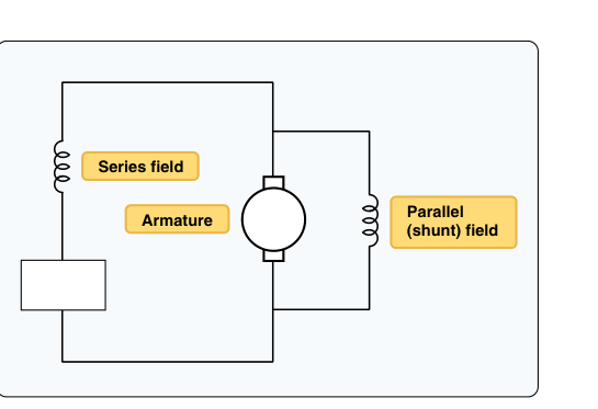
A starter-generator is fundamentally a DC compound-wound or shunt-wound motor/generator built into a single housing. It connects mechanically to the engine accessory gearbox through a drive pad, spinning at a ratio determined by the gearbox design. The unit has both series field windings (used during the motor/starting phase) and shunt field windings (used during the generator phase), along with an armature, commutator, and brush assembly — construction that is closely related to conventional DC motors and generators, but engineered to handle the thermal and mechanical stresses of both operating modes.
The Starting Phase
When the pilot initiates a start, high-amperage DC current from the battery or external ground power is routed through a start relay (contactor) to the starter-generator. During this phase, the unit operates predominantly as a series-wound motor, meaning battery current flows through both the series field windings and the armature. This series-dominant winding arrangement produces very high starting torque at low speeds — exactly what is needed to accelerate a gas turbine's compressor from rest through the phases of a normal start: motoring, light-off, and acceleration to idle.
As the engine accelerates, back-electromotive force (back-EMF) increases in the armature, naturally reducing current draw and torque in a characteristic motor curve. The engine's fuel control introduces fuel and ignition at the correct point during this motoring sequence (typically called the start speed or light-off speed), and the combined torque of the motor plus the expanding combustion gases drives the engine toward idle RPM.
The Transition to Generator Mode
A critical moment in the starting sequence is the cutout speed or self-sustaining speed — the point at which the engine can sustain its own rotation through combustion without external mechanical assistance. This threshold is defined by the specific engine manufacturer and varies considerably by engine model; always verify the applicable speed in the engine's specific AMM rather than relying on a general percentage. At or near this point, the starting circuit is automatically opened by the start relay and an undercurrent relay (or equivalent logic in modern systems) de-energizes the motor field circuit.
Almost simultaneously, the generator field circuit is established through the voltage regulator. Now the shunt field winding is energized from the aircraft's bus, residual magnetism in the field poles is reinforced, and the rotating armature begins producing output voltage. The voltage regulator senses output voltage and modulates field current to maintain a constant regulated output — typically 28 volts DC on most turbine aircraft using this architecture. A reverse-current relay or generator control unit (GCU) also prevents the battery from motoring the generator backward if output voltage drops below battery voltage.
Electrical Components in the System
- Start contactor (relay): A heavy-duty relay that routes battery or external power to the starter-generator during the start phase. It must handle hundreds of amperes and is rated for the inrush current of the motor.
- Undercurrent relay: Monitors armature current; when current drops to the point that the engine is approaching self-sustaining speed, it signals the control circuit to cut out the starter phase.
- Voltage regulator: Controls field current to maintain constant generator output voltage (nominally around 28 V DC, per manufacturer specification) across varying engine speeds and electrical loads.
- Reverse-current cutout relay or GCU: Disconnects the generator from the bus if output voltage falls below bus voltage, preventing motoring of the generator by the battery.
- Current limiter / line contactor: Protects wiring and the machine itself from sustained overload currents.
Construction and Cooling
Because the starter-generator must dissipate significant heat during both high-current motoring and continuous generator operation, cooling is critical. Most units are air-cooled by a blower integral to the unit itself or by ducted ram air. The cooling airflow passes through internal passages around the armature and field windings. Some installations incorporate a separate cooling air inlet with a filter and outlet duct that vents overboard. The FAA's Aviation Maintenance Handbook (General, FAA-H-8083-30) and Powerplant handbook (FAA-H-8083-32) note that restrictions in the cooling air supply are a significant cause of starter-generator failures, and inspectors should verify duct integrity and filter cleanliness at every scheduled inspection.
The brush and commutator assembly requires particular attention. Carbon brushes wear with normal use, and brush length must be measured and compared against manufacturer minimums. The commutator surface should be smooth, with no grooving, pitting, or copper deposits. Brush spring tension must also be within specification to ensure proper contact without excess wear. Out-of-specification brush tension is one of the more common maintenance findings on these units.
Why It Matters — Safety and Maintenance Relevance
A failed starter-generator has immediate operational consequences. If the unit fails in the generator mode during flight, the aircraft reverts to battery power only — a time-limited situation that demands immediate load-shedding and diversion planning. If it fails during a start attempt, the engine may not reach light-off speed, leading to a hung start, hot start, or no-start condition, each of which can cause significant engine damage if not recognized and aborted promptly.
From a maintenance standpoint, proper torque on the drive pad mounting, integrity of the gearbox drive coupling, and correct terminal connections are all critical. A loose terminal on the high-amperage start circuit creates resistance heating that can melt insulation and cause arcing. All terminal torques must be verified per the manufacturer's maintenance manual (AMM), not generic standards.
Key Numbers and Rules
- Typical output voltage: 28 V DC nominal for most turbine aircraft starter-generator systems; exact regulation tolerance is set by the manufacturer and must be verified in the applicable AMM.
- Start current: Inrush current during engine start is high and varies significantly by installation — wire sizing and contactor ratings must be selected to accommodate the specific surge current called out in the manufacturer's data.
- Self-sustaining speed: Varies by engine model; there is no single FAA-published percentage of N1 or N2 — always verify in the specific AMM.
- Brush inspection interval: Defined entirely by the manufacturer's maintenance program; no FAA-standardized interval exists. Replace when worn to the manufacturer's minimum length limit.
- Cooling air: Ensure no restrictions; typically inspect inlet filter and duct integrity at every scheduled inspection interval per the maintenance manual.
- Regulated voltage tolerance: Set by the manufacturer for the specific installation; check with a calibrated voltmeter under rated load per the AMM procedure rather than assuming a fixed tolerance.
Common Test Traps
- Confusing operating phases: The FAA test expects you to know that during the start phase, the unit is wired as a motor (consuming power), and during normal flight it is a generator (producing power). Candidates sometimes reverse this relationship.
- Series vs. shunt field use: During motoring, series windings provide high starting torque; during generating, shunt field control via the voltage regulator maintains constant voltage. Know which winding does which job.
- Undercurrent relay function: Some candidates confuse the undercurrent relay (which senses motor current dropping as the engine becomes self-sustaining) with an overcurrent protector. They serve different purposes.
- Cooling is not optional: Test questions about starter-generator failures commonly involve restricted cooling. Always associate premature failure or overheating with inadequate cooling airflow.
- Brush length is a go/no-go item: A brush that is too short cannot maintain proper spring tension against the commutator and will arc, causing commutator damage. This is not a monitor-and-continue finding; brushes at or below minimum length must be replaced immediately.
Mastering the starter-generator system means understanding it as a single electromechanical machine operating in two distinct modes, controlled by a coordinated set of relays and a voltage regulator. For the AMT Powerplant test, focus on the function of each control component, the importance of cooling, and the inspection requirements for brushes and commutator surfaces. In practice, these systems are highly reliable when properly maintained — and their compact, dual-purpose design is a testament to elegant aerospace engineering.