The magneto ignition system is the heartbeat of a reciprocating aircraft engine, firing spark plugs with precision timing independent of the aircraft's main electrical system. While most student mechanics encounter the conventional high-tension magneto first, the low-tension magneto represents an important engineering alternative that solved real problems in high-altitude and large-engine applications. Knowing how each system generates, transforms, and delivers electrical energy — and why engineers chose one over the other — is critical knowledge for the FAA Powerplant knowledge test and for safe maintenance practice.
How the High-Tension Magneto System Works
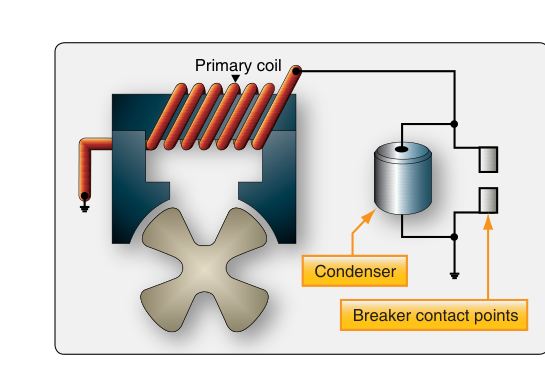
A high-tension magneto is a self-contained alternating-current generator, transformer, and distributor rolled into a single unit. Inside the magneto housing, a permanent magnet rotor spins past a coil assembly. The coil has two windings wound on a laminated soft-iron core: a primary winding of relatively few turns of heavy wire, and a secondary winding of thousands of turns of very fine wire. Together these form an automotive-style ignition coil built directly into the magneto.
As the rotating magnet approaches the position of greatest magnetic flux change, the contact points (breaker points) open. This abrupt interruption of current in the primary winding causes a sudden collapse of the magnetic field. By transformer action, the collapsing field induces a very high voltage — typically 15,000 to 20,000 volts — in the secondary winding. A capacitor (condenser) wired across the points absorbs the energy surge that would otherwise arc across the opening points, protecting them and sharpening the primary current collapse to make the secondary output even crisper.
That high-voltage pulse travels from the secondary winding through a high-tension lead — a thick, heavily insulated cable — to the distributor block. The distributor rotor, driven in sync with the magneto shaft, directs each pulse to the correct cylinder's spark plug at exactly the right moment in the firing order. The entire high-voltage path — from the secondary winding, through the distributor, through the ignition lead, to the spark plug — is carried at full voltage.
How the Low-Tension Magneto System Works
The low-tension system takes a fundamentally different approach. The magneto itself generates only a low-voltage alternating current in its single (primary-style) coil. This low voltage — generally cited as being on the order of a few hundred volts, though exact figures vary by design — is distributed through relatively thin, lightly insulated wiring to a separate transformer coil located at each individual cylinder. Only at that point is the voltage stepped up to spark-plug firing levels by the individual transformer.
Because the high-voltage path is extremely short (essentially just from the small transformer to the adjacent spark plug), the system avoids running kilovolt-level energy through long cables routed across the engine and airframe. Each cylinder's individual coil is small, lightweight, and positioned close enough to the spark plug that insulation demands on the distribution wiring are dramatically reduced.
Why the Difference Matters: Engineering Trade-Offs
The high-tension system dominated general aviation because of its simplicity and compactness. One magneto contains all the voltage-transformation hardware, and the wiring — though heavily insulated — is straightforward to route and inspect. Troubleshooting is relatively intuitive: a weak spark, misfiring, or complete ignition failure can usually be traced through the distributor block and individual ignition leads.
The low-tension system was developed primarily to address two problems that plagued large, high-powered aircraft engines and high-altitude operations:
- Flashover at altitude: At high altitudes, reduced air density lowers the dielectric strength of air. Long high-tension leads routed through unpressurized bays can arc — flash over — to airframe structure or to adjacent leads, causing misfires or fires. Low-tension distribution eliminates this risk because only low voltage travels those long paths.
- Radio interference (EMI): Long high-tension leads act as antennas, radiating electromagnetic interference that disrupts radio communications. Low-tension distribution greatly reduces this radiation. Shielded ignition leads in high-tension systems partially address EMI, but the low-tension approach eliminates most of the problem at its source.
- Long ignition lead runs on large radial engines: On large round (radial) engines with many cylinders arranged in multiple rows, routing heavily insulated high-tension leads to every cylinder without flashover was mechanically challenging. Individual low-tension transformers at each cylinder simplified that geometry enormously.
The trade-off is increased complexity and weight at the cylinder level — each cylinder carries its own transformer — and more potential failure points. Inspection and maintenance require attention to each individual coil unit, not just the centralized magneto.
Key Numbers and Rules
- High-tension secondary voltage: Typically 15,000–20,000 volts (some sources reference up to 20,000 V depending on engine type and magneto design).
- P-lead grounding: In both systems, the magneto is made safe (grounded out) by connecting the primary circuit to ground through the ignition switch P-lead. When the P-lead is disconnected or broken, the magneto is live regardless of switch position — a critical safety point.
- Magneto timing: High-tension and low-tension systems both require precise timing of the breaker-point opening (or, in electronic magnetos, the equivalent trigger) relative to top dead center (TDC) of each piston. Incorrect timing is an airworthiness issue on both system types.
- Dual ignition requirement: Most certificated reciprocating aircraft engines require two independent ignition systems (two magnetos, firing two spark plugs per cylinder) per 14 CFR Part 33.37 (Ignition system) engine certification standards. This redundancy applies to both high- and low-tension architectures.
- Ignition lead inspection: FAA AC 43.13-1 guidance covers inspection of ignition harnesses for chafing, cracking, carbon tracking, and proper insulation resistance. High-tension leads must pass insulation resistance tests; low-tension distribution wiring has lower voltage requirements but the individual coils must also be tested.
- Magneto drop limits: During the engine run-up, each magneto is checked independently. Excessive RPM drop or a large differential between the two magnetos indicates a problem requiring investigation before flight; the specific maximum drop and allowable differential (commonly cited figures for many engines are around 150 RPM max drop and 50 RPM max differential) are engine/POH specific and must be verified against the applicable manufacturer data rather than memorized as a universal number.
Practical Maintenance Considerations
For the AMT working on a high-tension system, the most common maintenance tasks include inspecting and replacing breaker points, servicing the condenser, checking the distributor block for carbon tracking or cracks, and inspecting ignition leads for insulation integrity. Carbon tracking — a thin conductive carbon path burned along the surface of distributor blocks or lead insulators — is a classic high-voltage phenomenon that can cause intermittent misfires and must be addressed by replacing the affected component.
On a low-tension system, the individual cylinder coils must each be inspected for secure mounting, condition of insulation, and electrical output. Because these coils sit close to the cylinder head, they are exposed to significant heat cycling and vibration, which can eventually crack coil windings or degrade their potting compound. An AMT must follow the engine or airframe manufacturer's maintenance manual for specific inspection intervals and test procedures for low-tension coil units.
In both systems, always treat the ignition system as potentially live during maintenance. Even with the ignition switch in the OFF position, a broken or disconnected P-lead means the magneto primary is not grounded and can fire if the propeller is moved. Always ground the magneto P-lead to the airframe and verify the magneto is electrically dead before working near the propeller or ignition components.
Common Test Traps
- Assuming the ignition switch makes a magneto safe: The FAA frequently tests whether applicants understand that the ignition switch grounds the magneto (it doesn't disconnect it). A broken P-lead leaves the magneto hot even with the switch OFF.
- Confusing where voltage is stepped up: In a high-tension system, voltage transformation happens inside the magneto. In a low-tension system, it happens at each cylinder's individual coil. Getting these reversed is a common answer-choice trap.
- Overlooking flashover as the main low-tension advantage: The FAA test expects you to know that reduced flashover risk at altitude — not weight savings or cost — was the primary engineering driver for low-tension systems on large and high-altitude engines.
- Carbon tracking location: Tracks form on the surface of insulating materials, not through them. A component showing carbon tracking must be replaced, not cleaned and reused, because the surface path is permanently compromised.
- Condenser (capacitor) function: The condenser does not store energy to help fire the spark plug. Its job is to absorb the primary current surge when the points open, preventing arcing at the points and sharpening the field collapse that induces the high secondary voltage. Confusing its role is a classic distractor on the written test.