Spark plugs are among the most frequently inspected and serviced components in a reciprocating aircraft engine. Every power stroke begins with a precisely timed electrical spark jumping across a small gap inside the engine cylinder, igniting the compressed fuel-air mixture and releasing the energy that turns the propeller. When plugs are in good condition and correctly matched to the engine, combustion is efficient and reliable. When they are fouled, worn, or of the wrong type, the consequences range from rough running and power loss to pre-ignition, detonation, and in-flight engine failure. For the Aviation Maintenance Technician (AMT), understanding spark plug types, selection criteria, and proper servicing procedures is not optional — it is foundational to every engine inspection.
Aircraft spark plugs differ substantially from automotive plugs. They must withstand extreme thermal cycling, high cylinder pressures, corrosive combustion byproducts from aviation fuels, and vibration loads that would destroy an ordinary plug within hours. The FAA Aviation Maintenance Handbook — Powerplant (FAA-H-8083-32) provides the authoritative guidance on selection and servicing, and it is the primary reference for this discussion.
Spark Plug Construction and Types
An aircraft spark plug consists of a steel shell, a ceramic insulator, a center electrode, and one or more ground electrodes. The shell threads into the cylinder head and provides the ground path; the center electrode is electrically isolated by the ceramic core and carries the high-voltage ignition pulse from the magneto. The gap between the center and ground electrode(s) is where the spark occurs.
Massive-Electrode Plugs
The most common type found in general-aviation reciprocating engines is the massive-electrode spark plug. These plugs use relatively large, solid electrodes — typically nickel alloy — that can withstand significant erosion before the gap widens beyond serviceable limits. Massive-electrode plugs are robust and tolerant of the operating conditions found in most piston engines. Their larger electrode mass does mean they require a slightly higher voltage to fire compared to fine-wire types, but they are far less expensive and are widely available.
Fine-Wire Plugs
Fine-wire spark plugs use very thin center electrodes made from iridium, platinum, or tungsten. Because a sharper electrode concentrates the electric field more effectively, fine-wire plugs fire at lower voltages, place less strain on the ignition system, and resist fouling better under low-power and cold-operating conditions. They also erode more slowly, meaning gap growth is minimal over long service intervals. Fine-wire plugs are more expensive but are increasingly specified for turbocharged engines and high-performance applications where ignition reliability is paramount. The AMT must always consult the engine manufacturer's Type Certificate Data Sheet (TCDS) and the applicable Airworthiness Directives (ADs) to confirm which plug types are approved for a specific engine.
Shielded vs. Unshielded Plugs
Modern aircraft spark plugs are almost universally shielded. The shielding — a metal shell that surrounds the top of the plug and the ignition lead connector — suppresses radio-frequency interference (RFI) generated by the high-voltage spark. Unshielded plugs, once common in older aircraft, are rarely encountered in certificated aircraft today. Shielded plugs use a standardized connector that mates with the shielded ignition harness; the AMT must never mix shielded and unshielded components in a single ignition system.
Reach and Heat Range
Two additional selection parameters are reach and heat range. Reach is the length of the threaded portion of the plug shell; using the wrong reach can cause the plug to protrude into the combustion chamber (causing hot spots and detonation) or sit too far back in the well (causing carbon bridging). Heat range describes how efficiently the plug transfers heat from its firing tip to the cylinder head. A hot plug has a longer insulator nose that retains more heat, keeping the tip clean by burning off deposits — useful in engines that run cool or at low power settings. A cold plug has a shorter insulator path, dissipates heat quickly, and is used in high-compression or turbocharged engines that already run at elevated combustion temperatures. Installing a plug that is too hot for the application risks pre-ignition; a plug that is too cold will foul rapidly. Selection must always follow the engine manufacturer's specifications exactly.
Spark Plug Condition and Inspection
FAA-H-8083-32 outlines the inspection criteria that AMTs apply during each spark plug removal. After cleaning, each plug is visually examined for the following:
- Normal condition: Light tan to gray deposits, minimal electrode erosion. The plug is cleaned, re-gapped, and returned to service or rotated.
- Oil fouling: Wet, oily deposits indicate oil is entering the combustion chamber — worn piston rings, valve guide seals, or excessive oil in the induction system. The plug should be replaced and the cause investigated.
- Lead fouling: Hard, lead-compound deposits (often gray or brown lumps) result from the tetraethyl lead (TEL) additive in 100LL avgas. Lead fouling is promoted by extended low-power operation. Plugs may sometimes be cleaned and returned to service, but severe bridging requires replacement.
- Carbon fouling: Dry, black, sooty deposits from an excessively rich mixture, prolonged idling, or a malfunctioning carburetor. Address the root cause before reinstalling plugs.
- Electrode erosion and gap growth: The electrode gap widens with use. When the gap exceeds the manufacturer's maximum (commonly around 0.016–0.021 inches for massive-electrode plugs, varying by type), the ignition system must produce higher voltage to fire the plug, stressing the magneto and harness and risking misfire at altitude.
- Cracked or chipped insulators: A plug with a damaged ceramic insulator must be discarded; a cracked core can arc internally, causing misfires or total ignition failure.
- Worn or damaged threads and gasket seats: Cross-threaded or corroded shell threads weaken the cylinder-head installation. Any plug with damaged threads is rejected.
Spark Plug Cleaning and Gapping
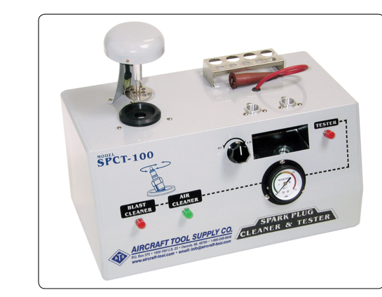
Approved cleaning methods include abrasive blasting (using a purpose-built spark plug cleaner that directs fine abrasive — typically aluminum oxide — around the insulator nose) followed by compressed-air blowout. Vibrating or wire-brushing electrode tips is not an approved practice, as it can embed abrasive particles or leave metallic debris that causes bridging. After cleaning, plugs are visually re-inspected under magnification.
Gapping is accomplished with a round wire feeler gauge — never a flat feeler gauge. A flat gauge can contact the electrode incorrectly and provide a false reading on worn or rounded electrodes. The gap is adjusted by carefully bending the ground electrode only; the center electrode must never be bent or struck. The correct gap tolerance is found in the engine or plug manufacturer's service data.
After gapping, each plug is tested in a pressurized spark plug tester that fires the plug under a simulated compression load (typically 80–100 psi of air pressure). The plug must fire consistently without misfiring, internal arcing, or visible damage. Plugs that misfire under pressure but fire at atmospheric pressure are unacceptable — altitude reduces air density and increases the voltage required to fire; a marginal plug that works on the ground may fail at cruise altitude.
Installation Procedures
Correct installation is as important as correct selection. Key steps include:
- Inspect the spark plug well in the cylinder head for thread condition, debris, and the seating surface. A thread chaser (not a tap) can be used to clean corroded threads without removing material.
- Install a new copper crush gasket on each plug; never reuse a gasket. The gasket seals combustion pressure and provides the electrical ground path through the shell to the cylinder head.
- Apply a small amount of approved anti-seize compound to the shell threads, avoiding the first two threads and keeping compound away from the electrodes and firing end. Excessive anti-seize on the firing tip is a fouling hazard.
- Thread the plug in by hand until snug, then torque to the value specified in the engine manufacturer's maintenance manual — typically in the range of 300–420 inch-pounds for 18mm plugs, but always verify. Under-torqued plugs can loosen and blow out; over-torqued plugs can crack the insulator or damage cylinder-head threads.
- Rotate plugs between top and bottom positions and between cylinders at each inspection interval. Top plugs run hotter and are more prone to lead fouling; bottom plugs run cooler and are more prone to oil and carbon deposits. Rotation equalizes wear across the set.
- Connect the shielded ignition lead and tighten the coupling nut to the specified torque — finger-tight plus one-quarter turn is a common guideline, but consult the applicable IPC/manual.
Why Spark Plug Maintenance Matters
Aircraft engines rely on dual ignition — two independent magnetos, each firing its own set of spark plugs in every cylinder. A properly maintained plug set is essential for the dual-ignition system to provide its intended redundancy and improved combustion efficiency. During the run-up mag check, an excessive RPM drop on a single magneto (or a total RPM below limits) often indicates a fouled or failed plug. There is no single FAA-mandated mag drop number that applies to every aircraft — the applicable limit is always the value published in the specific aircraft's AFM/POH or engine operating instructions. Ignoring an out-of-limits drop and dispatching the flight is a serious airworthiness violation. Because spark plug condition directly affects combustion quality, power output, fuel efficiency, and cylinder head temperature, plug maintenance is one of the highest-value, highest-frequency tasks in piston-engine upkeep.
Key Numbers and Rules
- Typical spark plug gap range for massive-electrode plugs: 0.015–0.021 inches (always verify against manufacturer's data).
- Use a round wire feeler gauge for gapping — flat gauges are prohibited.
- Test plugs under at least 80 psi air pressure in a pressurized tester before reinstalling.
- Torque 18mm plugs to approximately 300–420 inch-pounds (confirm in the engine manual).
- Mag drop limit during run-up: there is no single universal FAA figure — always check the specific aircraft's AFM/POH or engine operating instructions, which commonly reference maximum drop values and a maximum differential between magnetos.
- Rotate plugs (top to bottom) at every 100-hour or annual inspection.
- Never reuse copper crush gaskets.
- Always use the plug type specified on the engine TCDS — substitution requires FAA approval.
Common Test Traps
- Heat range confusion: Students often mix up hot and cold plugs. Remember: a hot plug retains heat (long insulator path) and is used in cool-running, low-compression engines; a cold plug dissipates heat quickly and is used in hot, high-compression or turbocharged engines. Installing a hot plug in a high-performance engine risks pre-ignition.
- Flat vs. round gauge: The FAA tests this repeatedly. The correct tool for gapping aircraft spark plugs is a round wire feeler gauge. Selecting a flat feeler gauge is a classic wrong answer.
- Gasket reuse: Never reuse copper crush gaskets. Questions may imply reuse is acceptable if the gasket looks undamaged — it is not.
- Anti-seize on the firing tip: Anti-seize compound must be kept away from the electrode end and the first threads. Applying it too liberally causes fouling and can affect torque readings.
- Ground electrode only for gapping: Only the ground electrode is bent to adjust the gap. The center electrode must never be bent. Attempting to adjust the center electrode cracks or weakens the insulator.