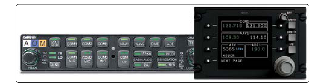
Modern aircraft cockpits can host a daunting array of radios, navigation receivers, warning systems, and intercommunication units — all producing or requiring audio signals at the same time. The audio control panel (ACP), sometimes called an audio selector panel or audio management unit, is the central hub that organizes this complexity. It allows flight crew members to choose which radio they transmit on, which signals they monitor through the headset or cockpit speaker, and at what volume. Working closely with the ACP is the interphone system, which provides direct voice communication between crew stations inside the aircraft — cockpit to cabin, cockpit to ground crew, and station to station — entirely independent of the aircraft's external radio systems.
For the aviation maintenance technician (AMT), understanding how these systems are designed, interconnected, and tested is essential. Faults in audio routing can silently degrade safety by preventing crews from hearing ATC, navigation audio idents, or critical aural warnings. Maintenance personnel must be able to isolate failures, inspect wiring and connectors, and verify system operation to return the aircraft to an airworthy state.
The Audio Control Panel: Architecture and Function
The ACP sits between the flight crew's headsets/microphones and all the aircraft's communication and navigation transceivers. At the most fundamental level, it contains a network of audio buses — shared electrical pathways — onto which different receiver outputs can be connected or disconnected by switches or relays. When a crew member presses the transmit key (PTT — push-to-talk) for a selected radio, the ACP connects that microphone signal to the correct transmitter while simultaneously muting or managing other audio to reduce distraction.
A typical ACP provides selector switches for each installed communication radio (COM 1, COM 2, HF, etc.) and each navigation receiver (VOR, ILS, ADF, DME, marker beacon). Separate controls often govern speaker versus headset output and allow individual volume adjustment for each source. The number of ACPs installed and the degree of redundancy varies by aircraft type and manufacturer — transport-category aircraft commonly have an ACP at each pilot station, and some installations include an additional unit at an observer or relief crew position — but this configuration is not standardized across all aircraft. Each ACP can independently manage its own audio without affecting the other stations, though all connect back to a common distribution network.
In glass-cockpit and fly-by-wire aircraft, the ACP function may be integrated into an Audio Management Unit (AMU) or Audio Management System (AMS), which performs the same routing functions but uses digital signal processing and ARINC 429 or ARINC 629 data buses for control signaling rather than simple relay logic. Regardless of the technology, the underlying principle remains the same: select the source, route the audio, control the level.
Transmit Selection and Interlock Logic
A critical design feature of any ACP is the transmit interlock. Only one transmitter may be keyed at a time on a given frequency to avoid simultaneous transmissions that would block communications. When a crew member presses PTT on COM 1, the ACP logic prevents any other station from simultaneously keying COM 1. It may also momentarily mute the associated receiver to prevent audio feedback — sometimes called sidetone management. Sidetone is the controlled amount of the crew member's own voice fed back into their headset to confirm that the microphone is active; too much sidetone is distracting, too little makes the crew member feel they are transmitting into silence.
Interphone Systems
The interphone system is a separate, dedicated internal communication network. It does not transmit externally; instead, it connects crew stations within and around the aircraft. There are typically three sub-systems:
- Flight Interphone: Connects the captain, first officer, and observer stations on the flight deck. Allows private crew coordination without using external radios.
- Cabin Interphone: Links the cockpit with individual flight attendant panels at cabin crew stations and galleys. Used for passenger announcements (PA) and crew coordination.
- Ground Crew (Service) Interphone: Provides jacks at external service points — nose gear bay, wing roots, ground power panel — so maintenance personnel can plug in a headset and communicate with the flight deck during engine starts, pushback, or ground checks. This is also known as the ground interphone or maintenance interphone.
Each interphone subsystem is usually powered from a dedicated bus and has its own amplifier and switching logic. A call system is closely associated with the interphone: pressing a call button activates a chime or light at the destination station to alert the occupant that someone wishes to communicate. The PA (passenger address) system may share amplifier hardware with the cabin interphone but is treated as a distinct function — it is one-way (cockpit to passenger cabin) and uses overhead loudspeakers rather than crew headsets.
System Components and Wiring
An audio control system comprises several categories of hardware that the AMT must be familiar with:
- Audio control panels/AMUs: The main selector and routing units at each crew station.
- Amplifiers: Boost low-level microphone signals and receiver audio to drive headsets, speakers, and PA horns. Amplifiers may be solid-state Class D designs in modern aircraft.
- Mixing networks: Passive resistor networks or active summing circuits that combine multiple audio sources (e.g., VOR ident + ILS glide-slope ident) into a single monitor channel.
- Relays and switching units: Electromechanical or solid-state devices that physically route audio between buses on ACP command.
- Wiring and shielded cables: Audio signals are low voltage (typically millivolts to a few volts) and highly susceptible to electromagnetic interference (EMI). Proper shielding, grounding of shield drain wires at one end only, and separation from high-current power wiring are essential maintenance considerations.
- Connectors and jacks: XLR-style or proprietary aviation connectors at headset jacks; service interphone jacks at external panels. Corroded or bent pins are a common fault source.
Why This Matters for Airworthiness
An inoperative or degraded audio system directly affects the crew's ability to communicate with ATC, monitor navigation signals, and coordinate with ground personnel — all safety-critical functions. Under 14 CFR Part 91 and the aircraft's minimum equipment list (MEL), specific audio system components may be required operative for dispatch. For example, an inoperative interphone between the cockpit and cabin attendants is typically addressed through the operator's specific MEL procedures, which may permit dispatch under defined conditions or require repair prior to further flight.
From a maintenance standpoint, audio system faults often present as intermittent problems related to loose connectors, cracked solder joints, or failing relay contacts. Because audio signals are electrically quiet (small voltages, low currents), even a high-resistance fault in a shield ground can inject significant noise or hum. Technicians should use an audio test set or a known-good headset connected to the system to perform functional checks, following the manufacturer's AMM (Aircraft Maintenance Manual) procedures step by step.
Key Numbers and Rules
- Audio selector panels and audio management systems intended for installation on type-certificated aircraft are commonly manufactured and authorized under TSO-C50 (Audio Selector Panels and Systems), which establishes minimum performance and environmental qualification standards for the equipment; this is a manufacturing/authorization standard rather than a direct operating rule imposed on every transport aircraft.
- Wiring repairs to shielded audio cables must restore the original shield continuity and ground connection; improperly grounded shields can cause persistent hum and EMI coupling.
- Interphone and PA systems are addressed in the aircraft type certificate data sheet and are part of the approved type design — any modification requires FAA approval (STC or field approval).
- Service interphone jack wiring varies by aircraft type — on some installations plugging in a headset at the external jack activates the ground crew interphone circuit automatically, while others require a cockpit crew selection to enable the circuit. AMTs should verify the specific aircraft's wiring and AMM procedure when testing.
- Marker beacon receivers operate on a single fixed frequency of 75 MHz; this audio is routed through the ACP like other navigation audio but is also paired with visual annunciator lights, so technicians should confirm both audio and visual indications during functional checks.
Common Test Traps
- Confusing the interphone system with the radio system: The interphone is purely internal; it does not transmit externally. Selecting an interphone station does not key any airborne transmitter.
- Sidetone versus feedback: Sidetone is intentional and controlled. Loud squealing feedback indicates an audio loop fault (usually a headset jack wired incorrectly or a failed mute relay), not normal sidetone.
- Shield grounding: Grounding a coaxial audio shield at both ends creates a ground loop that introduces 60 Hz hum. The correct practice is to ground the shield at one end only — typically the amplifier or panel end.
- PTT interlock failures: If the transmit interlock relay fails in the closed (energized) position, the transmitter may become stuck on (stuck mic), blocking the frequency. This fault is often diagnosed by monitoring the radio while performing a ground interphone test.
- Confusing PA with cabin interphone: The PA system is one-directional (crew to passengers); the cabin interphone is bidirectional (crew-to-crew). Both may share an amplifier, but they use separate switching and cannot be treated as equivalent systems during troubleshooting.