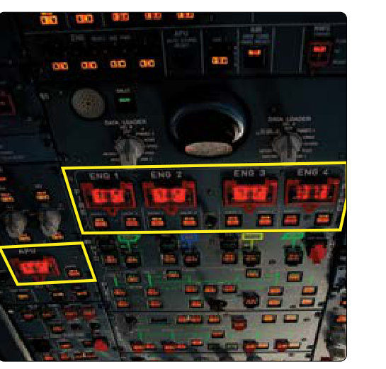
When an engine fire detection system senses heat or flame beyond safe limits, the crew's first line of defense is a set of mechanical and electrical controls located directly in the cockpit. These engine fire handles and the associated cockpit fire control panel are carefully engineered to execute a rapid, coordinated sequence of actions — shutting off fuel, hydraulic fluid, bleed air, and electrical power to the affected engine while simultaneously arming and discharging fire suppression agents into the engine nacelle or wheel well. For an Aviation Maintenance Technician (AMT) pursuing a Powerplant certificate, understanding how these systems are designed, what each component does, and why the sequence matters is both an exam requirement and a critical safety competency.
This article covers the physical and functional design of engine fire handles, the logic behind cockpit fire control panel layouts, and the maintenance considerations that keep these life-saving systems airworthy.
The Purpose and Design of Engine Fire Handles
An engine fire handle — sometimes called a fire pull handle or T-handle — is the primary pilot-actuated control for isolating a burning engine and arming its extinguisher system. On most transport-category and many regional turbine aircraft, the handle is a distinctive red, illuminated, T-shaped or circular pull knob located on the center pedestal or overhead panel. Its color, shape, and illumination are deliberate: in an emergency, there must be no confusion about which control to reach for.
When a fire warning is confirmed, the handle typically illuminates as well as triggers an aural alert (bell or warbler). The illumination is driven directly by the fire detection loop circuit, confirming that the warning is genuine before the crew acts. Pulling the handle — a deliberate, often two-step action requiring the pilot to first squeeze a locking mechanism or rotate the handle to overcome a guard — accomplishes several things simultaneously through a network of cables, push-pull rods, or electrical solenoids:
- Closes the engine fuel shutoff valve — stops fuel flow from the aircraft fuel system to the engine fuel control unit.
- Closes the hydraulic shutoff valve — isolates engine-driven hydraulic pump pressure from the aircraft hydraulic system, preventing hydraulic fluid from feeding the fire.
- Closes the bleed air shutoff valve — stops high-pressure hot air from the engine compressor from entering the bleed ducting where it could sustain or spread fire.
- De-energizes the engine-driven generator or alternator — removes the engine as an electrical source, isolating potential arcing hazards.
- Arms the fire extinguisher discharge circuit — connects the cockpit discharge switches to the squib-actuated extinguisher bottles so the crew can direct agent into the engine.
This single, integrated action is designed so that a pilot under extreme stress does not need to work through a long checklist of individual valve closures. Pulling the handle does the work automatically, leaving only the agent discharge decision to follow.
The Cockpit Fire Control Panel
The cockpit fire control panel is the broader assembly that houses the engine fire handles, agent discharge switches, system test controls, and warning annunciators. On older aircraft this panel may be a dedicated section of the center pedestal or overhead panel. On modern glass-cockpit aircraft, some functions are displayed on EICAS (Engine Indicating and Crew Alerting System) or ECAM (Electronic Centralized Aircraft Monitor) screens, but the physical fire handles themselves are almost universally retained as hard controls — redundancy is paramount.
Discharge Switches and Bottle Selection
After pulling the fire handle, the crew sees one or more illuminated discharge switches (sometimes called squib switches or agent release buttons). Many transport aircraft carry two extinguisher bottles total for the engine fire suppression system — often labeled Bottle 1 and Bottle 2, or Primary and Reserve — with plumbing that allows either bottle to be discharged into the affected engine, rather than each engine having its own dedicated pair. Exact bottle count and plumbing arrangements vary significantly by aircraft type, so AMTs must always consult the specific aircraft's system documentation. Pressing a discharge switch sends electrical current to the squib (a small pyrotechnic charge) in the selected bottle's outlet fitting. The squib fires, puncturing the bottle's frangible disk and releasing the pressurized Halon 1301 (or approved Halon alternative) agent through distribution tubing that sprays into the engine core compartment, fan compartment, or both, depending on aircraft design.
Some aircraft also allow cross-ship discharge, meaning a bottle normally plumbed to one engine can be directed to the opposite engine's nacelle. This gives the crew a second shot of agent if the initial discharge does not extinguish the fire. The crew monitors the fire warning light: if the handle light extinguishes after discharge, suppression was successful. If the light remains on after a reasonable dwell time (often 30 seconds), the second bottle is discharged.
Warning Lights, Test Circuits, and Fault Annunciation
The fire control panel incorporates test switches that allow technicians and crew to verify the continuity and integrity of the detection loops and squib circuits without actually discharging agent. A typical test sequence energizes the detection loop to confirm the cockpit warning lights, aural alerts, and handle illumination all function correctly. Squib continuity lights (sometimes called armed or ready lights) confirm that each discharge cartridge has an intact firing circuit. A missing or open circuit on a squib annunciates as a fault, alerting the AMT that the bottle must be serviced before flight.
Why This System Matters: Safety and Regulatory Grounding
Engine fire is among the most time-critical emergencies in aviation. Jet fuel and hydraulic fluid burn intensely; a nacelle fire that breaches structural components can sever control cables, damage adjacent fuel tanks, or compromise wing spars within seconds to minutes. The integrated design of the fire handle — one pull, multiple isolations — is a direct response to the need for speed and certainty under stress. The FAA's Aviation Maintenance Technician Handbook–Powerplant (FAA-H-8083-32), as well as manufacturer-specific data approved under type certificates, form the regulatory backbone for how these systems must be installed, tested, and maintained.
From an AMT standpoint, every component in the fire control chain — detection loops, handle mechanisms, valve solenoids, tubing, squibs, and extinguisher bottles — must be maintained in accordance with the aircraft manufacturer's Instructions for Continued Airworthiness (ICA) and applicable airworthiness directives (ADs). The agent bottles have hydrostatic test and recharge intervals. Squibs have calendar-based replacement schedules because the pyrotechnic charge can degrade over time. Neglecting these intervals is not merely a regulatory violation — it can mean a fire handle that pulls correctly but discharges nothing.
Key Numbers and Rules
- Halon 1301 is the most common agent in certified transport aircraft extinguisher bottles; alternatives (HFC-227ea, etc.) are approved on newer designs where Halon availability is limited due to environmental regulations.
- Two-bottle systems (often labeled Primary/Reserve or Bottle 1/Bottle 2) are common on many turbofan-powered transport aircraft, but the exact number of bottles and how they're plumbed to each engine varies by aircraft design — always verify against the specific aircraft's AMM.
- Squib replacement intervals are set by the manufacturer and tracked on the aircraft maintenance records — typically on the order of several years or flight hours; always consult the Aircraft Maintenance Manual (AMM).
- Bottle pressure checks are required at specified intervals; a low-pressure indication (below the green arc on the integral pressure gauge) means the bottle must be replaced or recharged before flight.
- Guard or locking mechanism on fire handles prevents inadvertent actuation — pulling requires deliberate force or a twist-then-pull sequence, specific to aircraft type.
- Fire detection loop continuity tests must be performed after any maintenance that disturbs the detection system wiring, per the AMM and 14 CFR Part 43 return-to-service requirements.
- Cross-ship discharge capability is aircraft-specific; not all designs provide it — AMTs must know the specific system architecture of the aircraft they maintain.
Common Test Traps
- Confusing arming with discharging: Pulling the fire handle arms the extinguisher circuit but does NOT discharge agent. A separate discharge switch (squib switch) must be pressed to release the agent. Many students assume the pull alone fires the bottles — it does not.
- Assuming bottle arrangement is identical across all aircraft: Many transport-category aircraft carry two extinguisher bottles total, often plumbed so either bottle can be discharged into the affected engine, rather than a dedicated primary and reserve bottle per individual engine. The FAA Powerplant knowledge test may ask about primary and reserve bottle arrangements — always expect two shots available, but confirm the specific architecture for the aircraft in question.
- Forgetting bleed air isolation: Students often list fuel and hydraulic shutoff when describing fire handle actions but forget that bleed air shutoff is also part of the handle's integrated function. Hot compressed air sustaining a fire is a real hazard.
- Thinking squib lights confirm agent quantity: Squib continuity (armed/ready) lights only confirm the firing circuit is intact — they do NOT verify that the bottle contains adequate agent. Bottle pressure gauges and weight checks confirm charge status.
- Overlooking bottle hydrostatic test requirements: Extinguisher bottles must be hydrostatically tested at intervals specified in the AMM regardless of agent quantity. A bottle that has never been discharged still requires periodic testing — time-in-service matters, not just usage.
Mastering engine fire handle and fire control panel operation requires understanding not just the sequence of events but the engineering logic behind each step. Every valve closure, every circuit arm, and every squib check has a specific safety rationale. As an AMT, your role is to ensure that when a crew pulls that red handle in an emergency, every downstream action occurs exactly as designed — because lives depend on it.