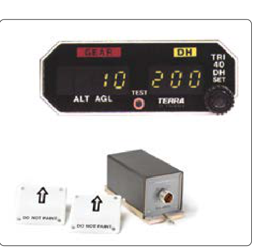
A radio altimeter — also called a radar altimeter or low-range radio altimeter (LRRA) — is a specialized electronic instrument that measures the aircraft's height above the ground directly beneath it. Unlike a barometric altimeter, which infers altitude from atmospheric pressure and requires correction for local conditions, the radio altimeter uses timed electromagnetic pulses to measure actual terrain clearance. This distinction makes it indispensable for Category II and Category III instrument landing system (ILS) approaches, automatic landing systems (autoland), ground proximity warning systems (GPWS), and terrain awareness and warning systems (TAWS). For the Aviation Maintenance Technician working on airframe systems, understanding how the radio altimeter functions — and why antenna installation is so precisely regulated — is essential for both airworthiness and crew safety.
How the Radio Altimeter Works
The radio altimeter operates on the principle of measuring round-trip signal travel time. A transmitter antenna radiates a continuous or pulsed radio frequency signal downward toward the earth's surface. The signal reflects off the terrain or water below and is received by a separate receive antenna. The system's processor calculates the time elapsed between transmission and reception. Because electromagnetic waves travel at the speed of light (approximately 186,000 miles per second, or about 300,000 kilometers per second), even the tiny fractions of a second required to traverse altitudes of a few hundred feet can be measured and converted to height above ground level (AGL).
Most commercial and transport-category aircraft radio altimeters use frequency-modulated continuous wave (FM-CW) technology. Rather than transmitting a brief pulse and waiting for an echo, the FM-CW system continuously sweeps the carrier frequency through a defined range — typically centered around 4.3 GHz in the C-band. The transmitter frequency rises and falls in a sawtooth or triangular wave pattern at a known rate. When the reflected signal returns, it carries a slightly older version of that sweep. By comparing the instantaneous frequency of the transmitted signal against the received signal, the processor derives a beat frequency that is directly proportional to altitude. A higher beat frequency means more time elapsed, which means greater height. This technique allows very accurate measurement at low altitudes — typically from −20 feet (to confirm gear-down ground contact) up to 2,500 feet AGL on most systems, though some designs extend to 5,000 feet.
The processed altitude data is displayed on a dedicated radio altimeter indicator — often a drum-pointer or electronic flight display presentation — and simultaneously fed to other avionics: the flight management system (FMS), GPWS or TAWS computers, autoland systems, decision height (DH) alerting circuits, and traffic collision avoidance systems (TCAS) that require terrain proximity data. The analog output is commonly a DC voltage that varies linearly with altitude, while modern digital installations use ARINC 429 data buses to distribute the information throughout the aircraft.
Antenna Design and Location
The radio altimeter relies on two flush-mounted blade or flat-plate antennas installed on the underside of the fuselage — one for transmitting, one for receiving. The separation of the transmit and receive antennas is not arbitrary; it is carefully calculated to eliminate direct coupling between them. If the transmitting antenna's signal could reach the receive antenna directly (without bouncing off the ground), the processor would interpret that signal as a false ground return at zero feet, corrupting the reading. Physical separation and directional shielding in the antenna design suppress this direct-path leakage.
Antenna placement is governed by the aircraft manufacturer's Structural Repair Manual (SRM) and installation drawings, as well as applicable FAA Technical Standard Orders (TSO). TSO-C87 (Airborne Low-Range Radar Altimeter) specifies the performance standards that compliant equipment must meet, including altitude accuracy and response time. Any alteration to antenna location must be coordinated with an approved data source — an FAA-approved Supplemental Type Certificate (STC), an Engineering Order, or a field approval with FAA oversight — because even small changes can degrade system accuracy.
Key Placement Criteria
- Fore-aft positioning: Antennas are mounted beneath the fuselage, generally aft of the nose gear bay and forward of the main gear, where the fuselage skin is relatively flat and undistorted during pressurization cycles. Placement beneath areas of significant fuselage curvature or skin flexing is avoided.
- Lateral separation: The transmit and receive antennas are separated laterally (typically 20 to 36 inches apart on transport-category aircraft) to minimize direct coupling while keeping both antennas within the same relatively flat belly panel.
- Ground plane integrity: A proper ground plane — the surrounding metallic fuselage skin — is essential for the antennas to radiate and receive correctly. Repairs involving non-conductive composite patches, bonding compound fill, or interruptions in skin continuity near the antennas must be evaluated for their effect on ground plane characteristics.
- Obstructions and shadowing: Nothing should obstruct the antennas' vertical radiation pattern. Nearby doors, access panels, antennas for other systems, and structural protrusions can scatter or block the downward-directed beam, creating multipath errors or dead zones.
- Dual-system installations: Many transport-category aircraft have two (or three) independent radio altimeter systems for redundancy during Category III autoland operations. Each system has its own pair of antennas, and the sets must be positioned to avoid cross-coupling — the transmitter of System 1 must not be received by the receive antenna of System 2, which would produce a false common-mode reading.
Installation and Maintenance Considerations
Coaxial cables connecting the antennas to the radio altimeter transceiver are a critical maintenance concern. The cables must be low-loss, properly shielded, and of the exact length specified by the manufacturer. Cable length affects the electrical signal path delay; an unauthorized cable splice or substitution with a different impedance cable introduces path length errors or reflections that offset the altitude reading. All connectors must be properly torqued and protected against moisture ingress, because water in a coaxial connector causes signal attenuation and impedance mismatches that directly degrade accuracy.
The antennas themselves are subject to physical damage from ground equipment strikes, bird impact, and erosion. A cracked or delaminated antenna radome — the protective cover over the antenna element — admits moisture, which detunes the antenna and causes reflection pattern changes. During routine maintenance, technicians should inspect antennas for cracks, delamination, missing sealant around the antenna flange, and corrosion of the mounting hardware. Any antenna whose radome is compromised must be replaced or repaired in accordance with the manufacturer's approved data before return to service.
After any maintenance that could affect the system — including antenna replacement, cable replacement, fuselage skin repair near the antenna area, or avionics box replacement — a functional test must be performed. This typically involves a ramp test using a specialized radio altimeter test set that simulates a ground return signal at known heights. The system's displayed altitude must match the simulated height within the manufacturer's specified tolerance, which is commonly ±2 feet or 2% of indicated altitude, whichever is greater, for the critical low-altitude regime (0 to 100 feet).
Why It Matters
The stakes around radio altimeter accuracy are unusually high. During a CAT III ILS approach, a crew may continue descent to a decision height as low as 50 feet AGL — or even to a no-decision-height (CAT IIIc) autoland — based directly on what the radio altimeter reports. A system that reads five feet lower than actual terrain gives a false sense of additional clearance; one that reads high may trigger an early go-around command from the autoland system. Either error can be fatal close to the runway threshold. GPWS and TAWS use radio altimeter data to compute terrain closure rate; erroneous data causes nuisance alerts or — far more dangerously — suppressed genuine warnings. For this reason, aircraft operating under FAA-approved autoland programs must demonstrate radio altimeter system accuracy and integrity during certification and must maintain it throughout the aircraft's service life.
Key Numbers and Rules
- Typical operating frequency: approximately 4.3 GHz (C-band FM-CW signal).
- Typical altitude range: −20 feet to 2,500 feet AGL on most transport systems.
- Accuracy requirement (low range): ±2 feet or ±2% of indicated altitude, whichever is greater.
- Governing TSO: TSO-C87 for low-range radar altimeters.
- Antenna separation (typical transport): 20 to 36 inches lateral spacing between transmit and receive antennas.
- Any alteration to antenna placement requires FAA-approved data (STC, Engineering Order, or equivalent).
- Post-maintenance functional test is mandatory using a calibrated radio altimeter test set.
Common Test Traps
- Confusing radio and barometric altimeters: The radio altimeter measures height above ground (AGL); the barometric altimeter measures pressure altitude (MSL). They display different values except at sea-level airports with standard pressure.
- Assuming any coaxial cable can substitute: Cable impedance, shielding quality, and precise length are specified values. An incorrect cable introduces signal delays or reflections that shift altitude readings, making the substitution an airworthiness issue even if the cable physically fits.
- Overlooking cross-coupling in dual installations: Test questions may address why dual-system antennas must be arranged to prevent one system's transmitter from feeding the other's receiver — a direct-path signal would produce a falsely low or erratic altitude reading common to both channels, defeating redundancy.
- Ignoring composite repair effects on ground plane: Non-conductive composite patches near the antenna can disrupt the ground plane and alter the antenna's radiation pattern, degrading accuracy without any visible change to the antenna itself.
- TSO-C87 applicability: Technicians should know that the TSO defines minimum performance standards for the certified equipment; the aircraft's approved maintenance manual (AMM) and installation drawings define exactly how and where the equipment must be installed on a specific airframe.