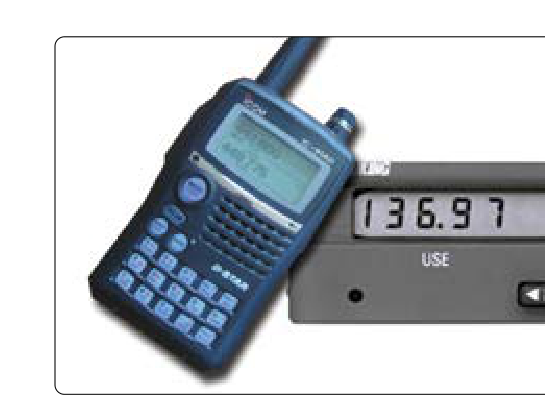
Very High Frequency (VHF) communication radios are the primary voice communication tool used in civil aviation worldwide. Operating in the frequency band between 118.000 MHz and 136.975 MHz, these transceivers allow pilots to communicate with air traffic control, UNICOM, MULTICOM, ATIS, and other aircraft. For the AMT airframe technician, a working knowledge of how these systems function — from the antenna through the transceiver to the cockpit control head — is critical for proper installation, inspection, and troubleshooting. Regulatory compliance under 14 CFR and manufacturer data must guide every maintenance action.
This article covers VHF comm radio theory, system components, antenna installation and maintenance, common faults, and the practical inspection procedures that keep these systems airworthy. While avionics technicians with the appropriate ratings perform most radio repairs, airframe AMTs regularly handle antenna work, wiring, bonding, and the inspection tasks called out in approved maintenance data.
How VHF Communication Systems Work
VHF radio waves travel primarily by line-of-sight propagation. Because the signals do not reliably follow the curvature of the Earth, range is limited by the altitude of the transmitting and receiving stations. A practical rule of thumb is that usable range increases with altitude — a pilot at 10,000 feet AGL can communicate with a ground station at a distance far greater than one at 1,000 feet AGL. This characteristic makes VHF ideal for aircraft-to-ground and aircraft-to-aircraft communications in controlled airspace where altitude provides the needed line-of-sight path.
The aviation VHF comm band is divided into channels spaced either 25 kHz or, increasingly, 8.33 kHz apart. The 8.33 kHz channel spacing was introduced in Europe to accommodate growing demand, and modern radios sold for international operations must support it. In the United States, 25 kHz channel spacing remains the standard for domestic operations. The transceivers use amplitude modulation (AM), specifically double-sideband AM, rather than the frequency modulation (FM) used in commercial broadcast radio. AM was chosen because it is more tolerant of simultaneous transmissions — when two stations transmit at once on AM, receivers hear a mix of both, rather than one signal completely suppressing the other as FM's capture effect would cause.
System Components
A typical airborne VHF comm installation consists of four main elements: the control head (or integrated display unit in modern glass-panel aircraft), the transceiver (which may be a remote-mounted box or an integrated panel-mounted unit), the coaxial transmission line, and the antenna. In older aircraft, the control head and transceiver are combined in a single panel-mounted unit. In transport-category and many general aviation aircraft, the transceiver is rack-mounted in the avionics bay, and a separate control head in the cockpit handles frequency selection and squelch.
The transceiver both transmits and receives on a single antenna, switching rapidly between functions. When the pilot presses the push-to-talk (PTT) switch, a relay or solid-state switch connects the transmitter to the antenna and disconnects the receiver; upon release, the receiver reconnects. This is why a pilot cannot hear incoming transmissions while transmitting.
The coaxial cable (coax) connecting the transceiver to the antenna must have the correct impedance — typically 50 ohms — and must be in good condition. Damaged dielectric, loose connectors, or water intrusion increase standing wave ratio (SWR), reducing transmitted power and potentially damaging the final amplifier stage of the transmitter. The AMT should inspect coax runs for chafing, kinking, and moisture damage during routine inspections.
The antenna on most general aviation aircraft is a quarter-wave blade antenna, resonant near the center of the VHF comm band. Physical blade antennas used for VHF comm are typically shorter than a true free-space quarter-wavelength due to base-loading and dielectric shortening techniques used by manufacturers, so technicians should reference the specific antenna's installation data rather than a single fixed length figure. They rely on the aircraft skin as a ground plane to complete the electrical circuit — this is why proper bonding of the antenna mount to the airframe structure is critical. Poor bonding increases antenna system resistance, degrades performance, and can cause interference.
Antenna Installation and Bonding Requirements
Antenna installation must follow the aircraft manufacturer's approved data or a Supplemental Type Certificate (STC) if the original installation is being modified. The AMT must ensure the antenna is mounted to structure capable of handling the aerodynamic and inertial loads, sealed to prevent moisture intrusion into the airframe, and electrically bonded to the airframe. AC 43.13-1B, the FAA's Acceptable Methods, Techniques, and Practices for Aircraft Inspection and Repair, provides detailed guidance on antenna installations that AMTs frequently use as acceptable data for minor repairs and inspections.
Electrical bonding is measured with a bonding resistance check. The resistance between the antenna base and the nearest main airframe structure should be extremely low — typically less than 0.003 ohms (3 milliohms) per AC 43.13-1B guidance. Higher bonding resistance degrades antenna performance and can induce noise into the audio system. Bonding jumpers, if required, must be kept as short as possible and must be inspected for corrosion and security.
On composite airframes, the absence of a conductive ground plane requires a different approach. Many composite aircraft use embedded copper mesh or foil in the skin around the antenna, or a dedicated ground plane plate, to simulate the metallic ground plane. The AMT must follow manufacturer-specific data for these installations because the standard metal-airframe assumptions do not apply.
Why It Matters: Airworthiness and Safety
A failed comm radio in controlled airspace can strand an aircraft without clearance and create a collision risk. Under 14 CFR Part 91, operations in Class A, B, C, and D airspace require two-way radio communication capability. A failed antenna or transceiver that goes undetected during maintenance can lead to an airworthiness violation and, more critically, a safety hazard. The AMT's role is to catch antenna deterioration, connector corrosion, chafed wiring, and intermittent PTT switch faults before they cause an in-flight failure.
Audio panel faults are another practical concern. Many aircraft use a separate audio panel to route comm audio to headsets, speakers, and intercom systems. A faulty audio panel relay can make a perfectly functional transceiver appear dead. The AMT troubleshooting a comm radio complaint should systematically verify each component — antenna, coax, transceiver, and audio panel — rather than assuming the radio itself is at fault.
Key Numbers and Rules
- VHF Comm frequency band: 118.000 MHz to 136.975 MHz
- Modulation type: Amplitude Modulation (AM), double-sideband
- Channel spacing (US): 25 kHz standard for domestic operations; 8.33 kHz spacing required for some international operations
- Antenna impedance: 50 ohms (coaxial system)
- Bonding resistance: Less than 0.003 ohms (3 milliohms) per AC 43.13-1B guidance
- Antenna length (quarter-wave blade): Physically shorter than a free-space quarter-wavelength due to base-loading; consult manufacturer/installation data for exact length
- Propagation: Line-of-sight; range increases with altitude
- Regulatory authority: FCC licenses aircraft radio stations (except for domestic-only operations under certain conditions); 14 CFR Part 91 governs operational requirements
- Inspection basis: Aircraft maintenance manual, AC 43.13-1B (for acceptable methods on minor repairs), and applicable STCs
Common Maintenance Faults and Troubleshooting
The most frequently encountered VHF comm faults in field maintenance include: corroded antenna connectors (PL-259 or BNC types), which increase SWR and cause transmitter overheating; chafed coaxial cable against structure or through grommets; loose antenna base mounting hardware, which degrades bonding; stuck or intermittent PTT switches on yokes or control wheels; and water intrusion into the antenna base or coax connector, which is particularly common on lower-fuselage antenna installations.
When a pilot reports low transmit range, the first steps for the AMT are to perform a visual inspection of the antenna and its base, check bonding resistance, inspect the coax connector at both the antenna and transceiver ends, and verify that the correct antenna is installed for the frequency range. An SWR meter in-line with the coax during a bench test can quantify how much energy is being reflected back from a mismatched antenna system.
Common Test Traps
- AM vs. FM confusion: Aviation VHF comm uses AM, not FM. Many students confuse this with VHF navigation (VOR), which also uses AM, or assume aviation uses FM because commercial broadcast FM is more familiar.
- Bonding resistance value: The 3 milliohm (0.003 ohm) maximum bonding resistance figure is specific and testable — do not confuse it with the higher values acceptable for other bonding applications.
- Composite ground plane: On composite aircraft, the skin does not serve as a ground plane. Assuming standard metal-airframe antenna installation practices apply to composite structures is a dangerous mistake.
- FCC vs. FAA jurisdiction: The FAA governs airworthiness and operational requirements; the FCC regulates the radio station license. AMTs sometimes confuse which agency's rules apply to which aspect of the installation.
- PTT stuck in transmit: A PTT switch stuck in the transmit position blocks the entire frequency for all users and can be mistaken for a dead receiver. Always verify the PTT is releasing fully when troubleshooting a no-receive complaint.