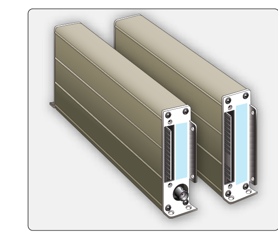
The Instrument Landing System (ILS) is the most widely used precision approach aid in aviation, and two of its core components — the localizer and the glideslope — are the radio receivers that decode the ground-based signals and translate them into needle deflections on the cockpit indicator. For an airframe technician, understanding how these receivers work, how they are installed and interconnected, and how they are tested is essential both for certification and for keeping aircraft airworthy in instrument meteorological conditions (IMC).
The ILS as a whole combines up to five elements: the localizer, the glideslope, outer and middle marker beacons, and approach lighting. Of these, the localizer and glideslope receivers are the active electronic components mounted in the avionics bay (or integrated into modern multifunction avionics units) that the airframe technician is most likely to inspect, remove, or troubleshoot. This article focuses on how those two receiver subsystems work, how they interface with aircraft systems, and what the FAA requires for their continued airworthiness.
How the Localizer System Works
The localizer transmitter sits at the far end of the runway — the departure end — and broadcasts on one of forty dedicated VHF frequencies between 108.10 MHz and 111.95 MHz (odd tenths only in that band). It produces two overlapping lobes of signal: a 90 Hz modulation lobe on the left side of the runway centerline (as seen from the approach end) and a 150 Hz modulation lobe on the right side. On centerline, both signals are received in equal depth of modulation (DDM = 0). If the aircraft drifts right of centerline, the 150 Hz signal predominates; the receiver detects this imbalance and deflects the course deviation indicator (CDI) needle to the left, commanding the pilot to fly left — back to center.
The localizer receiver itself is essentially a narrow-band VHF receiver tuned to the selected frequency. Its internal circuitry demodulates the composite RF signal, separates the 90 Hz and 150 Hz audio components, and feeds the difference signal to the CDI. Full-scale deflection (the point at which the needle hits the edge of its travel) corresponds to approximately ±2.5° from centerline, although the total angular width is designed so that full-scale deflection represents ±350 feet from centerline at the runway threshold for a typical runway. This means the system is more sensitive close in and progressively more sensitive as the aircraft descends toward the threshold — a built-in feature that encourages precise tracking on final.
Course width is adjustable at the ground station but is standardized to produce that ±350 ft threshold coverage. The usable range of a localizer is at least 18 nautical miles within ±10° of course, and at least 10 nautical miles within ±35° of course, at the altitudes used for the approach.
How the Glideslope System Works
The glideslope transmitter is located beside the runway, roughly 750 to 1,250 feet from the approach end, and it broadcasts on one of forty paired UHF frequencies between 329.15 MHz and 335.00 MHz. Importantly, the glideslope frequency is automatically paired with the localizer frequency — the pilot tunes the localizer, and the avionics automatically select the correct glideslope frequency. This pairing is hardwired into the receiver design and is verified during installation.
Like the localizer, the glideslope transmitter creates two overlapping lobes: the 90 Hz lobe above the glidepath and the 150 Hz lobe below the glidepath. The standard glidepath angle is 3° above horizontal, though some airports use slightly steeper angles for obstacle clearance. On glidepath, DDM is zero and the glideslope needle (a horizontal needle on the CDI or attitude direction indicator) centers. If the aircraft climbs above glidepath, the 90 Hz signal predominates and the needle deflects downward, telling the pilot to descend. If the aircraft descends below glidepath, the 150 Hz signal dominates and the needle rises. Full-scale deflection on the glideslope corresponds to approximately ±0.7° from the glidepath, making it significantly more sensitive than the localizer needle.
Because the glideslope operates at UHF frequencies, it uses a separate antenna — typically a blade or receive-only antenna mounted on the lower fuselage or nose area — distinct from the VHF nav antenna used for the localizer. Separation of these antennas is critical; interference between them degrades signal quality. The airframe technician must verify proper antenna location, bonding, and coaxial cable routing per the aircraft's STC or type certificate data sheet (TCDS).
Receiver Installation and Interconnection
In traditional installations, a dedicated nav receiver handles the localizer signal. Modern glass-cockpit and integrated avionics units (such as those from Garmin, Collins, or Honeywell) combine the localizer receiver, glideslope receiver, VOR receiver, and sometimes GPS into a single line-replaceable unit (LRU). Regardless of form factor, the outputs of both receivers must connect to:
- The CDI or HSI: Lateral deviation from the localizer and vertical deviation from the glideslope are displayed as needle deflections.
- The autopilot/flight director (if installed): Many autopilots can fly an ILS approach coupled to the localizer and glideslope outputs.
- The marker beacon receiver: Though a separate unit, marker audio and visual annunciators (outer, middle, inner) are often wired through the same avionics panel.
- Annunciator lights and flags: A red NAV or GS warning flag appears on the indicator whenever signal strength is insufficient or the receiver detects an invalid signal. Flag circuits must be verified during installation and maintenance.
Wiring must be shielded to prevent RF interference, and connector integrity is critical — a loose pin in the deviation signal line can cause false flag warnings or erratic needle movement that may not be immediately obvious on the ground.
Airworthiness and Regulatory Requirements
Under 14 CFR Part 43, any installation or alteration of ILS receiver equipment is a major alteration requiring an FAA Form 337 unless it is accomplished under an existing STC or the manufacturer's Instructions for Continued Airworthiness (ICA). The aircraft must be returned to an airworthy condition, and the work must be performed by or under the supervision of an appropriately rated technician.
For IFR certification, 14 CFR §91.205(d) requires that ILS equipment installed for IFR operations must be in proper working order. Advisory Circular AC 43.13-1B (Acceptable Methods, Techniques, and Practices) provides acceptable methods for antenna installation, coaxial cable routing, and bonding practices that the airframe technician should follow.
ILS receivers used under IFR must undergo a VOR/ILS check within the preceding 30 days per 14 CFR §91.171, which specifies acceptable check methods including FAA-designated VOT, airborne checks, and ground checkpoints. While the pilot is responsible for this check, the technician must ensure the receiver is capable of passing it after any maintenance.
Key Numbers and Rules
- Localizer frequency range: 108.10–111.95 MHz (odd tenths), VHF.
- Glideslope frequency range: 329.15–335.00 MHz, UHF — auto-paired with localizer.
- Localizer course width: Approximately ±2.5°; full-scale ≈ ±350 ft at threshold.
- Glideslope angle: Typically 3°; full-scale deflection ≈ ±0.7°.
- Localizer usable range: 18 NM within ±10° of course; 10 NM within ±35°.
- Modulation signals: 90 Hz = fly right/fly down (left/above on needle); 150 Hz = fly left/fly up (right/below on needle).
- IFR currency check: Within 30 days, per 14 CFR §91.171.
- Major alteration documentation: FAA Form 337, per 14 CFR Part 43.
Common Test Traps
- Confusing 90 Hz and 150 Hz needle commands: Remember that 90 Hz predominance means the aircraft is on the side where 90 Hz is stronger — to the left of the localizer course or above the glideslope — but the needle deflects the opposite direction, commanding the pilot to fly toward the beam center.
- Assuming glideslope is VHF: The glideslope operates at UHF (329–335 MHz), not VHF. This affects antenna type, placement, and the fact that a separate UHF antenna is required.
- Forgetting auto-pairing: The glideslope frequency is never manually tuned; it is automatically paired when the localizer frequency is selected. A system that requires the pilot to separately tune glideslope is not a standard ILS installation.
- Ignoring the flag circuit: The NAV flag or GS flag is part of the receiver output circuit, not just a cosmetic indicator. An inoperative flag means the system cannot be used for IFR approaches, even if the needles appear to function normally.
- Treating back-course localizer as identical to front course: On a back-course approach, the localizer signal is the same transmitter but used from the other side. Needle sensing reverses unless the avionics are set to back-course mode. This is an installation and checkout consideration when verifying system logic.