Fabric covering is one of the oldest and most enduring methods of aircraft construction, used on everything from classic Piper Cubs to modern homebuilt aircraft. When new fabric is applied to an airframe, it typically appears loose and wrinkled — a condition that must be corrected before doping or finishing. The shrinkage process, accomplished through carefully controlled heat application, transforms that slack fabric into a taut, drum-like surface that is both aerodynamically smooth and structurally sound. For any AMT candidate working toward an airframe certificate, mastering the mechanics and technique of fabric shrinkage is essential, both for the practical test and for safe maintenance practice.
This article covers the full shrinkage process: how heat affects fabric at the fiber level, the tools and temperatures involved, the correct sequence of application, and the safety and airworthiness considerations that govern every step.
How Fabric Shrinkage Works
Modern aircraft fabric — whether polyester (such as Dacron-based products), cotton, or glass cloth — is woven from fibers that have an inherent tendency to contract when exposed to heat. For polyester fabrics, which dominate contemporary aircraft covering, this thermal shrinkage is particularly well-suited to aviation use because it is predictable, repeatable, and can produce very high surface tension without distorting the underlying structure.
When heat is applied to unsealed polyester fabric, the individual fibers relax and then contract as molecular bonds within the polymer chains reorganize. This contraction is distributed uniformly across the weave if heat is applied correctly, pulling the fabric tight across ribs, spars, and other structural members. The result is a surface that resists flutter, sheds airflow cleanly, and provides a stable base for the dope or other finishing coatings that follow.
It is critical to understand that heat shrinkage must occur before the fabric is sealed with dope or coating. Once a barrier coat is applied over the weave, the fabric's ability to shrink in response to heat is dramatically reduced. This is why the shrinkage step always comes first in the covering sequence, typically after the fabric has been attached to the structure but before any liquid finishing products are brushed or sprayed on.
Tools and Temperature Ranges
The primary tool for fabric shrinkage is a heat gun or a fabric iron — sometimes called a covering iron or sealing iron. Both are used in aircraft fabric work, but they serve slightly different purposes and require different handling techniques.
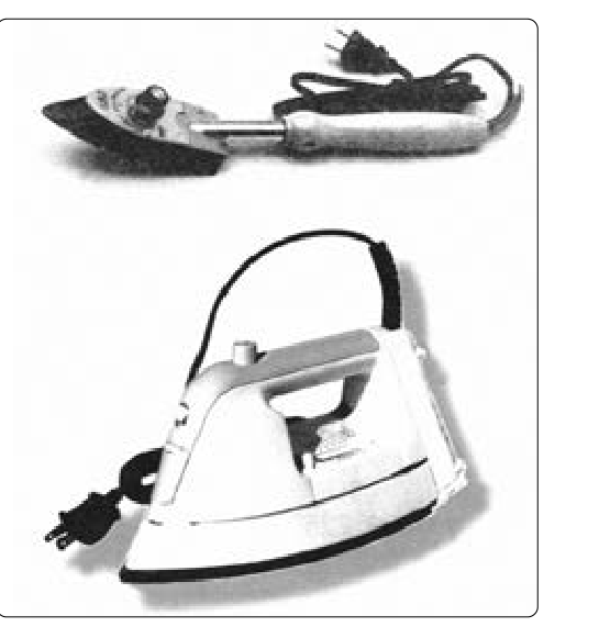
A fabric iron is a temperature-controlled iron resembling a household iron but designed specifically for aviation fabric work. Its flat, smooth sole plate allows direct contact with the fabric surface. The iron is set to a specific temperature and drawn across the fabric surface in steady, even strokes. The temperature setting is critical: too low, and the fabric will not shrink adequately; too high, and the fabric can be permanently damaged — scorched, melted in spots, or weakened structurally.
A heat gun is used when direct contact is impractical, such as around curved surfaces, ribs, or fasteners, or when a technician is performing a final tautening pass over a large surface. The gun directs a controlled stream of hot air across the fabric. Because the heat gun does not contact the surface directly, temperature regulation depends heavily on distance and dwell time.
For the most widely used polyester aircraft fabrics, manufacturers specify a two-temperature shrinkage process:
- First pass — low temperature (approximately 250°F / 121°C): This initial application is a light tautening pass. The fabric shrinks moderately, conforming closely to the airframe structure without reaching maximum shrinkage. This step locks the fabric in position and removes gross wrinkles.
- Second pass — high temperature (approximately up to 350°F / 177°C, per the applicable process): This final pass drives the fabric to near-maximum shrinkage, producing the characteristic taut surface. At this temperature, the polyester fibers contract fully. Exact shrinking temperatures vary between approved STC processes (for example, Ceconite versus Poly-Fiber/Stits systems), so these figures are general guidance only.
These temperatures are process-specific. The controlling document for a polyester fabric covering job is typically the STC holder's approved process manual or instructions (such as those published by Ceconite, Poly-Fiber, or Stits) under which the covering is accomplished. Approved data may also come from the aircraft manufacturer's data or, when no other data exists, AC 43.13-1B (Acceptable Methods, Techniques, and Practices — Aircraft Inspection and Repair). The AMT must always consult the specific approved data governing the fabric system being used — generic temperatures given here are starting points only, and the approved data governs. Deviating from approved temperatures can result in fabric that is under-tensioned (a safety hazard) or over-tensioned (risking structural damage to ribs and other light airframe members).
Sequence and Technique
Good technique in heat shrinkage is as important as the correct temperature. The process should proceed as follows:
- Inspect the applied fabric. Before any heat is applied, verify that the fabric is properly attached — cemented, stitched, or taped as required by the approved data — and that there are no foreign objects beneath the fabric surface.
- Perform the first low-temperature pass. Beginning at one edge of a panel and working toward the opposite edge, apply the iron or heat gun in smooth, overlapping strokes. Never hold the iron stationary; constant movement prevents hot spots. Work in a systematic pattern — typically from the leading edge aft, or from the center outward — so that shrinkage occurs evenly and does not create localized puckers.
- Allow the fabric to cool completely between the first and second passes. Applying high heat to fabric that is still warm from the first pass can cause uneven shrinkage or damage.
- Perform the second high-temperature pass using the same systematic pattern. After this pass, the surface should be uniformly taut with no visible sags or wrinkles.
- Inspect the completed surface. A properly shrunk panel will be smooth, taut, and free of distortion. Check for any hot spots — areas that appear glossy, discolored, or have a different texture — which indicate localized overheating.
Why It Matters
Fabric surface tension is not merely cosmetic. A loose or unevenly tensioned fabric surface can flutter at cruise airspeeds, creating destructive cyclic loads on the attachment points and ribs beneath. In severe cases, fabric flutter can tear loose from the structure entirely, with catastrophic consequences. Proper shrinkage ensures the fabric behaves as an integral part of the structure rather than a flapping membrane.
Additionally, a properly tensioned fabric surface provides the correct foundation for dope penetration. Nitrate or butyrate dope, and many modern coatings, rely on the fabric weave being uniformly open and taut so that the liquid can penetrate and form a cohesive film. Wrinkled or slack fabric creates irregular dope thickness, which can introduce weak spots in the finished surface.
From an airworthiness standpoint, the FAA requires that all fabric work be accomplished in accordance with approved data — either the STC holder's approved process manual, a manufacturer's maintenance manual, or AC 43.13-1B (Acceptable Methods, Techniques, and Practices — Aircraft Inspection and Repair) when no other data exists. The AMT is responsible for ensuring the correct data governs every step.
Key Numbers and Rules
- First shrinkage pass: approximately 250°F (121°C) — varies by the applicable approved process data.
- Second shrinkage pass: approximately up to 350°F (177°C) — varies by the applicable approved process data.
- Heat must be applied before any sealing coat or dope is applied to the fabric.
- The iron must remain in constant motion — never hold it stationary on the fabric.
- Allow fabric to cool fully between the low- and high-temperature passes.
- All fabric work must follow approved data: the STC holder's process manual, manufacturer's instructions, or AC 43.13-1B.
- A resonant, drum-like tone when tapped is a common informal field indicator of adequate tautness, not a formal FAA acceptance criterion.
- Excessive tension can distort or crack ribs — always verify that the airframe is rated for the fabric type and tension being applied.
Common Test Traps
- Reversing the temperature sequence: Some candidates assume the high-temperature pass comes first. It does not — the low-temperature pass always precedes the high-temperature pass to allow controlled, progressive shrinkage.
- Applying heat after doping: A sealed fabric surface cannot shrink properly. Heat application after the barrier coat is the wrong sequence and will not produce adequate tautness.
- Assuming one temperature fits all fabrics: Cotton and polyester fabrics have different shrinkage characteristics and temperature requirements, and different polyester STC processes (Ceconite, Poly-Fiber/Stits, etc.) specify their own temperatures. The approved data for the specific product governs — not a generic rule of thumb.
- Stationary iron application: Holding the iron in one place, even briefly, can scorch or melt the fabric. The FAA practical test expects candidates to understand that constant motion is mandatory.
- Overlooking structural limits: Over-shrinking fabric on a light airframe can bow or crack wooden ribs. The AMT must account for the structural strength of the underlying components when selecting and applying fabric products.