Every radio call, navigation signal, and transponder reply aboard a certificated aircraft depends on a reliable transmission path between the antenna and its associated avionics box. That path is almost always a coaxial cable — a precisely engineered conductor surrounded by insulation, a woven or foil shield, and an outer jacket — terminated at each end with an RF (radio frequency) connector. When this assembly is in perfect condition, signals travel with minimal loss and without interference. When it degrades, the results range from annoying static and reduced range to complete communication or navigation failure. For the Aviation Maintenance Technician (AMT) working on airframe systems, understanding how to inspect, diagnose, and properly repair coaxial cable and RF connectors is therefore a core competency, grounded in FAA guidance and sound electrical practices.
This article walks through the construction of coaxial cables, the most common failure modes encountered in service, step-by-step inspection procedures, approved repair and replacement techniques, and the testable knowledge points most likely to appear on the FAA Airframe knowledge exam.
Coaxial Cable Construction and How It Works
A coaxial cable is built around a central conductor — usually solid or stranded copper — that carries the RF signal. Surrounding it is a dielectric insulator, typically solid or foamed polyethylene or polytetrafluoroethylene (PTFE/Teflon), which maintains a precise, consistent spacing between the center conductor and the outer shield. That spacing determines the cable's characteristic impedance, the most important electrical property for RF work.
Over the dielectric sits the outer conductor, which serves two roles simultaneously: it completes the electrical circuit and it shields the inner conductor from external electromagnetic interference (EMI) while also preventing the cable from radiating energy that could interfere with other aircraft systems. In aircraft-grade cable this shield is most often a tightly woven braid of tinned copper wire; some designs add a foil layer beneath the braid for improved high-frequency shielding. The entire assembly is wrapped in an outer jacket of PVC, polyurethane, or another abrasion-resistant compound chosen for the environmental conditions expected in that aircraft zone.
Most aircraft communication and navigation systems use cable with a characteristic impedance of 50 ohms. Antenna and avionics manufacturers design their equipment to the same 50-ohm standard, so the cable, connector, and equipment form a matched system. A mismatch — caused by a wrong cable type, a damaged connector, or a crushed section that changes the dielectric spacing — creates reflections that reduce transmitted power and can damage sensitive receivers or transmitters.
RF Connector Types Used in Aircraft
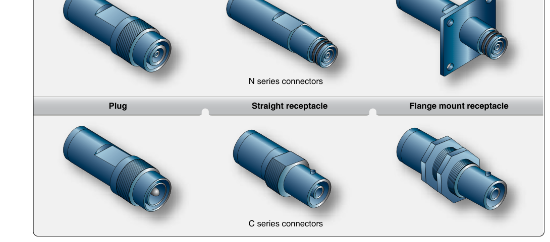
The most prevalent RF connector in general aviation and light transport aircraft is the BNC (Bayonet Neill–Concelman) connector, widely used on VHF navigation receivers, transponders, DME, and audio panels because it locks quickly with a quarter-turn bayonet coupling. Larger or higher-power applications such as HF radios and some VHF comm installations use the PL-259 connector, part of the UHF connector series; PL-259 is the male plug, and its mating female jack is designated SO-239. Precision navigation systems and other RF installations sometimes use TNC connectors, a threaded version of the BNC that offers greater vibration resistance and more stable performance at higher frequencies than a bayonet-coupled connector. Modern aircraft with GPS and Mode S transponders may also use SMA connectors on smaller antennas or internal wiring harnesses.
Regardless of type, every RF connector shares the same job: to continue the geometry of the coaxial cable — center conductor, dielectric, shield, and outer body — through the mechanical joint with zero change in impedance. Any disruption at the connector, such as a cold solder joint, a strand of braid touching the center conductor, or an air gap from a poorly seated connector body, introduces impedance discontinuity and signal loss.
Common Failure Modes
Coaxial assemblies in aircraft face a punishing environment. Temperature cycling from ground heat to high-altitude cold, vibration, moisture ingress, and the mechanical stress of routing through airframes all degrade the assembly over time. The most common failures the AMT will encounter include:
- Shield braid fraying or corrosion: Moisture wicks along the braid from a damaged jacket or poorly weatherproofed connector, causing green oxidation on tinned copper. Corroded braid increases resistance and reduces shielding effectiveness, leading to noise and interference in received signals.
- Dielectric compression or crushing: Coax routed through tight areas can be pinched by structure, fasteners, or other wire bundles. Crushing deforms the dielectric, changes the center-conductor-to-shield spacing, and alters characteristic impedance locally — creating a reflection point.
- Center conductor damage: The inner conductor may be pushed back into the dielectric during connector installation, or pulled forward under repeated flexing, creating an open or intermittent contact. Solid-conductor cables are more prone to work-hardening and cracking at repeated-flex points.
- Connector body looseness: BNC and TNC bayonet pins wear with repeated connect/disconnect cycles. A loose connection introduces intermittent continuity and can allow moisture past the connector body.
- Jacket damage and chafing: Anywhere the outer jacket chafes against structure — especially at bulkhead passthroughs without proper grommets — the jacket wears through, exposing the braid to moisture and eventually causing a short between shield and airframe structure where none should exist.
- Cold solder joints: On hand-soldered PL-259 or BNC connectors, inadequate heat during assembly leaves a dull, granular joint that may pass continuity testing but fails under vibration or temperature change.
Inspection Procedures
A thorough coaxial cable inspection begins with a visual check of the entire run. Trace the cable from the avionics bay to the antenna, looking for kinks, sharp bends tighter than the cable manufacturer's specified minimum bend radius, abrasion damage to the outer jacket, and areas where the cable contacts structure without protective sleeving or a proper cushion clamp. At every connector, inspect the outer body for corrosion, cracks, and security of the coupling mechanism.
After the visual check, use a calibrated ohmmeter or continuity tester for basic electrical checks. With connectors separated at both ends, verify: (1) center conductor continuity end-to-end with no open circuit; (2) shield continuity end-to-end; and (3) no continuity between center conductor and shield — a short between the two is an immediate cause for rejection of the assembly. This short-to-shield check is especially important because a shield strand inadvertently touching the center pin during connector installation is one of the most common technician-induced faults.
For a more complete picture, a time-domain reflectometer (TDR) sends a pulse down the cable and measures reflections returning from impedance discontinuities. The location and magnitude of each reflection can pinpoint a crushed section, a bad connector, or a damaged splice anywhere along the run — without disturbing the installation. Where TDR equipment is available, it is the preferred method for assessing cables longer than a few feet.
Antenna system health can also be assessed indirectly through VSWR (voltage standing wave ratio) measurement, which quantifies how well the transmitter, cable, and antenna are matched. A VSWR of 1:1 is a perfect match; as a general avionics industry guideline (rather than a specific FAA-published threshold), values above approximately 2:1 typically prompt further investigation of the cable or connector assembly.
Repair and Replacement Standards
When damage is limited to the outer jacket with the braid and dielectric intact, jacket damage may sometimes be repaired with approved self-amalgamating tape or heat-shrink tubing — but the technician must confirm that the cable's electrical characteristics are unaffected before returning it to service. Any mechanical damage that reaches the braid or dielectric, any short between center conductor and shield, and any open center conductor means the cable or connector assembly must be replaced.
Connector replacement follows a precise process. For soldered connectors: strip the cable to the dimensions specified in the connector manufacturer's instructions and the applicable aircraft maintenance manual; prepare the braid evenly; seat the connector body fully so the center pin engages correctly; and apply sufficient heat to achieve a shiny, smooth solder fillet without overheating the dielectric. Overheating causes the dielectric to melt and flow, permanently altering impedance. For crimp-style connectors, use only the die and tool combination specified by the connector manufacturer — an incorrect crimp leaves either a loose braid contact or a crushed center contact, both of which cause failure.
All repairs must comply with the applicable aircraft maintenance manual, the avionics manufacturer's installation data, and FAA Advisory Circular guidance on aircraft electrical wiring. New cable used in repairs must match the original cable's type designation, impedance, and temperature rating for the installation zone. Substituting a different impedance cable — even if it fits physically — will degrade system performance and could violate the avionics equipment's installation approval.
Key Numbers and Rules
- 50 ohms: Standard characteristic impedance for most aircraft communication and navigation coaxial cable.
- Center-to-shield short: Any measurable continuity between center conductor and shield is cause for immediate rejection.
- Minimum bend radius: Never exceed the cable manufacturer's minimum bend radius; the specific multiple of the cable's outer diameter varies by cable type and manufacturer specification, so always confirm the figure against the applicable cable data sheet rather than assuming a single blanket value.
- VSWR above ~2:1: A general avionics industry guideline (not a specific FAA-published figure) for triggering further investigation of cable, connector, or antenna condition.
- Shield coverage: Braid shield coverage varies by cable type and manufacturer — single-braid designs may provide less, double-shielded designs more — so consult the specific cable's manufacturer data; regardless of type, coverage significantly degraded by corrosion or physical damage compromises EMI protection.
- Tool compliance: Crimp connectors must be installed with manufacturer-specified tooling — an unapproved tool voids the connector's performance specification.
Common Test Traps
- Confusing impedance values: Test questions may offer 75 ohms (standard for video/cable TV) or 300 ohms (twin-lead) as distractors. Aircraft RF coax is 50 ohms.
- Overlooking a center-to-shield short: Students sometimes focus only on continuity of the center conductor and forget to verify that no short exists between center and shield — the FAA exam exploits this omission.
- Assuming jacket damage alone condemns the cable: Jacket damage alone does not automatically require cable replacement if the braid and dielectric are intact and electrical tests pass — but the damage must be properly repaired and the cause addressed.
- Misidentifying connector types: Know the visual difference between BNC (bayonet quarter-turn), TNC (threaded version of BNC), PL-259 (large, threaded), and SMA (small, threaded) — the exam may test identification and appropriate application.
- Neglecting minimum bend radius: Routing coax in too tight a bend is a common installation error; the exam may ask why a cable installed in a sharp bend causes signal problems even when it passes a simple continuity check.