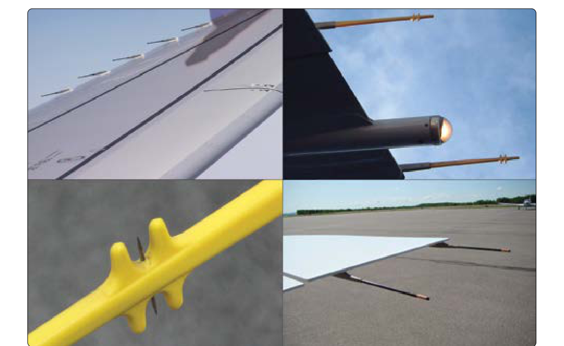
Every time an aircraft flies through the atmosphere, it accumulates electrostatic charge on its skin. Friction between air molecules, precipitation, dust, and ice crystals continuously deposits charge on the airframe. Without a controlled path for that charge to bleed away, the built-up static can discharge violently across the airframe in random arcs — generating broadband radio frequency (RF) noise that blankets communication and navigation receivers with static. Static discharge wicks, sometimes called static dischargers, solve this problem by providing a controlled, high-resistance path that allows charge to bleed off continuously and quietly into the surrounding air. Antenna bonding addresses a related but distinct challenge: ensuring that every antenna, avionics box, and structural panel shares the same electrical reference — the airframe ground — so that RF signals are not distorted, reflected, or attenuated by unwanted impedance differences. Together, these two disciplines form the foundation of electromagnetic compatibility (EMC) for certificated aircraft.
For the Aviation Maintenance Technician (AMT) working on airframe systems, understanding the theory behind static discharge and RF bonding is just as important as knowing the physical installation steps. The FAA's Aviation Maintenance Technician Handbook — Airframe (FAA-H-8083-31) addresses electrical bonding and static discharge as core maintenance topics, and the aircraft manufacturer's maintenance manual always governs specific installation details. This article brings both together to give you the depth you need for the AMT Airframe knowledge test and the shop floor.
How Static Charge Builds Up and Why It Is Harmful
Triboelectric charging occurs when two materials rub together and electrons transfer from one to the other. In flight, air molecules, water droplets, and ice crystals are continuously striking the aircraft skin, leaving it with a net positive or negative charge that can reach tens of thousands of volts. This charge is not dangerous to occupants in the way that lightning is — the energy levels are much lower — but the rapid, uncontrolled discharge across gaps in the airframe creates a sharp pulse of RF energy that spans a wide frequency range. VHF communications (118–136 MHz), VOR navigation (108–118 MHz), ADF (190–1750 kHz), and GPS (1575.42 MHz L1) receivers are all vulnerable. The result is the familiar hissing, crackling static heard in headsets during flight in precipitation or dry, turbulent air.
The problem is compounded by the fact that composite and painted surfaces are electrically resistive. Composite skins made of carbon fiber, fiberglass, or Kevlar do not conduct electricity the way aluminum does, so charge accumulates in isolated pockets rather than spreading evenly. Even on metal aircraft, paint and anodizing create local resistive barriers. Static wicks and bonding straps work together to eliminate these pockets and ensure charge has a continuous, low-resistance path back to a common ground point.
Static Discharge Wick Design and Function
A static discharge wick is a slender, pencil-like device typically 4 to 8 inches long. Its core is a carbon-impregnated resistive element — often a carbon fiber rod or a resistive plastic — with a pointed or bristled tip. The resistive core is essential: it limits current flow so that charge bleeds off gradually rather than in a sudden arc. Surrounding the core is a conductive outer sheath or braid that connects to the airframe structure. The tip geometry — fine bristles or a sharp point — concentrates the electric field at the tip, lowering the voltage at which corona discharge begins. Corona discharge is a slow, continuous ionization of air molecules at the tip, and it is far quieter from an RF standpoint than a random arc discharge elsewhere on the airframe.
Most wicks present an internal resistance in the range of 0.5 to 10 megohms (MΩ) from the tip to the base. This high resistance is intentional: it is high enough to prevent the wick from acting as an antenna or creating a short circuit to ground, yet low enough to bleed off accumulated charge faster than it can build to arc-discharge levels. During installation inspection, the AMT measures wick resistance with a calibrated megohm meter and compares the reading to the manufacturer's specified range. A wick that reads near zero ohms has a failed resistive element and should be replaced; one that reads open (infinite resistance) has a broken internal connection and is equally useless.
Static Wick Installation Requirements
Static wicks are installed at the trailing edges of control surfaces, wingtips, stabilizer tips, and other extremities — the points where the electric field is naturally strongest and where uncontrolled discharge would most likely occur. Specific locations are defined by the aircraft's type certificate data and the maintenance manual. The AMT must follow these approved locations precisely; adding or relocating wicks without engineering approval constitutes an unapproved alteration.
The mechanical attachment is usually accomplished with a screw-and-clamp or a threaded stud through the trailing edge structure. The electrical connection between the wick's conductive sheath and the airframe must have very low resistance — typically less than 0.1 ohm — measured from the wick base to the primary airframe structure. A corroded or painted contact surface under the mounting hardware will introduce resistance and defeat the purpose of the wick. The AMT must clean the mounting surface to bare metal, apply a conductive sealant if called for in the maintenance manual (especially on composite structures), and verify bonding resistance after installation. Thread-locking compounds should be non-insulating types unless the manual specifies otherwise.
On composite airframes, the wick base is often bonded with conductive epoxy to a metallic insert that is itself laminated into the composite structure. Some composite aircraft use conductive mesh or metallic foil plies in the lay-up specifically to provide a continuous static dissipation path; the wicks connect to this embedded conductor. Always verify that the composite structure has not been repaired in a way that interrupts the conductive path between the wick mount and the primary bonding network.
Antenna Bonding Requirements
An antenna operates by sensing or radiating RF energy relative to the airframe ground plane. If the coaxial cable shield — which is the antenna's ground return — sees a different electrical potential than the surrounding structure, that difference appears as noise or signal degradation. Proper antenna bonding ensures that the antenna's ground reference and the airframe structure are at the same potential across the frequency range of interest.
The bonding resistance requirement for antenna installations is more stringent than for static wicks. Most manufacturers specify a bonding resistance of less than 0.003 ohm (3 milliohms), per applicable bonding standards between the antenna ground plane and the primary airframe structure. This near-zero resistance is required to prevent the antenna from radiating or receiving on its own mounting hardware rather than its radiating element, and to protect sensitive receivers from ground loops. Achieving 3 milliohms requires clean metal-to-metal contact over a sufficient surface area, the use of conductive grease or alodine treatment (not paint), and properly torqued hardware.
The coaxial cable connecting an antenna to its avionics box must be routed away from other wiring that could couple interference into the center conductor. The outer braid of the coaxial cable should be bonded to the airframe at both ends of any long run. Avoid sharp bends that can kink the dielectric and change the cable's characteristic impedance, and never splice coaxial cable in the middle of a run unless a proper impedance-matched connector is used.
Bonding Straps: Selection and Inspection
Bonding straps — flat braided copper or aluminum jumpers — are used to bridge structural joints, control hinges, and access panel gaps that would otherwise create impedance discontinuities. The strap must be as short as practical; a long strap acts as an inductor at RF frequencies, effectively increasing impedance at high frequencies even if DC resistance is low. Width matters too — a wide, flat braid has lower RF impedance than a round wire of the same DC resistance. Inspect bonding straps at every inspection for corrosion, broken strands (more than 10–20% of strands broken is typically cause for replacement per the manufacturer), and loose hardware. A strap that rattles or is kinked has likely suffered fatigue cracking internally even if it looks intact externally.
Why It Matters: Safety and Airworthiness
A single failed static wick or a high-resistance antenna bond can make an aircraft's communication and navigation systems unreliable in the very conditions — instrument meteorological conditions, precipitation — when they are needed most. Beyond radio interference, high static charge buildup has been implicated in fuel ignition events during refueling if the refueling nozzle and the aircraft tank were at different potentials. Proper bonding of the entire airframe, including every antenna mount, access panel, and control surface hinge, is an airworthiness requirement, not merely a performance preference.
Key Numbers and Rules
- Static wick internal resistance: typically 0.5 MΩ to 10 MΩ tip-to-base (verify against manufacturer's spec).
- Static wick bonding resistance to airframe: less than 0.1 ohm at the mount point.
- Antenna bonding resistance: typically less than 0.003 ohm (3 milliohms) to primary airframe ground, per manufacturer/bonding standard specification.
- Bonding strap inspection: replace if more than approximately 10–20% of strands are broken or corrosion is present.
- Coaxial cable bends: minimum bend radius is typically ten times the cable outside diameter to prevent impedance change.
- Wick locations: trailing edges of all control surfaces, wingtips, and stabilizer tips as specified by the type certificate and maintenance manual.
- Measurement tool: use a calibrated milliohm meter or megohm meter appropriate to the range being measured — never a standard continuity light or uncalibrated ohmmeter for critical bonding checks.
Common Test Traps
- Confusing wick resistance ranges: students sometimes expect a good wick to have low (near-zero) resistance. The opposite is true — the resistive element is intentionally high (megohm range). A near-zero reading means the resistive core has failed.
- Mixing up bonding standards: static wick bonding at the mount is checked in ohms (less than 0.1 Ω), while antenna bonding is checked in milliohms (less than 3 mΩ). The antenna standard is far more stringent.
- Assuming paint is acceptable under bonding hardware: paint and anodizing are insulators. All bonding connections require bare metal-to-metal contact; the surrounding area may be resealed after installation per the manual.
- Wick placement on composites: on composite aircraft, the wick is worthless if the embedded conductive path in the laminate has been interrupted by a repair. Always trace the conductive path back to the primary ground.
- Coaxial cable splicing: inserting a butt splice or non-RF connector in a coaxial run changes the cable's impedance and is not an approved repair. The cable must be replaced full-length or repaired with a proper impedance-matched RF connector.