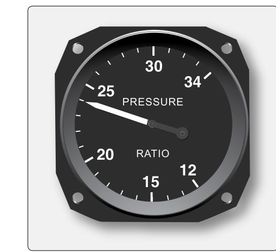
On many turbine-powered aircraft, the pilot cannot directly observe the thrust a jet engine is producing — there is no mechanical link between the spinning turbine and a simple gauge. Engine Pressure Ratio, or EPR, solves this problem elegantly. By comparing the total pressure at two carefully chosen stations inside the engine, EPR gives flight crews and maintenance technicians a reliable, real-time indication of how much thrust the engine is generating. For AMT Powerplant candidates, understanding how the EPR system works, how it is calibrated, and what can go wrong with it is essential both for the FAA knowledge test and for safe real-world engine maintenance.
EPR is defined as the ratio of turbine discharge total pressure (Pt5 or Pt7, depending on engine design) to engine inlet total pressure (Pt2). In plain terms, the system measures how much the engine has increased the total energy of the airflow from front to back. A higher ratio means more energy added, which translates directly to more thrust. An EPR of 1.0 would mean the discharge pressure equals the inlet pressure — essentially no thrust. Actual takeoff EPR values vary significantly by engine model, altitude, and atmospheric conditions and are established by the specific engine manufacturer's performance charts rather than a single universal range.
How the EPR System Works
The EPR indicating system relies on two pneumatic sensing probes and a differential pressure transmitter or transducer that converts the pressure ratio into an electrical or mechanical signal displayed on the cockpit indicator.
Inlet Pressure Sensing (Pt2)
A total pressure probe — essentially a pitot-style tube — is mounted at the engine inlet, typically in the inlet duct or on inlet guide vanes. This probe measures the total (ram plus static) pressure of the air entering the engine. Because this station is ahead of any compression, it reflects ambient conditions plus any ram pressure recovery from forward flight. Even small errors here will propagate through the ratio calculation, so probes are carefully designed to minimize turbulence ingestion and are usually heated to prevent ice accumulation.
Turbine Discharge Pressure Sensing (Pt5)
A second set of probes, typically an annular rake of multiple sensing ports arranged around the exhaust duct, measures total pressure downstream of the last turbine stage. Using multiple ports and averaging their signals compensates for pressure non-uniformities in the exhaust stream. On turbofan engines, this station is located in the exhaust gas stream before the exhaust nozzle, capturing the energy remaining after the turbines have extracted work from the gas. The ratio of this exit pressure to the inlet pressure defines EPR.
Transmitter and Indicator
The two pressure signals are routed to a differential pressure transmitter. In older analog systems, the transmitter is a mechanical bellows or diaphragm arrangement: inlet pressure acts on one side and discharge pressure on the other, with the resulting mechanical deflection driving a synchro or potentiometer. In modern FADEC-equipped (Full Authority Digital Engine Control) engines, high-accuracy pressure transducers convert both pressures to electronic signals, and the engine control computer calculates EPR digitally, then sends the result to a digital cockpit display. In either case, the cockpit indicator is calibrated in EPR units — a dimensionless ratio — rather than in absolute pressure units.
Calibration of the EPR System
Calibration ensures that the EPR reading in the cockpit accurately reflects the true pressure ratio inside the engine. Inaccurate EPR indications are a serious safety concern: a reading that is too high could cause a crew to apply insufficient thrust for takeoff, while a reading that is too low could cause over-thrust and structural or mechanical damage.
Probe Calibration and Positioning
The inlet probe position is critical. The probe must be located upstream of any compressor-induced pressure rise but positioned to capture true ram recovery. Manufacturer-approved locations are established during engine type certification using extensive test-cell measurement. On the discharge side, the number, position, and angular orientation of the rake probes are equally prescribed. If any probe is damaged, repositioned, or replaced with a non-approved part, the EPR calibration is invalid and the engine must be returned to service only after an approved calibration check.
Transmitter and System Zero Check
On the ground with the engine shut down and inlet and discharge pressures equal to ambient, the EPR indicator should read 1.00 (or very close to it, depending on system design). This ground zero check is performed at each maintenance inspection interval specified in the Aircraft Maintenance Manual (AMM). A reading that deviates significantly from 1.00 with the engine off indicates a pneumatic leak in one of the sense lines, a blocked probe, a faulty transducer, or an indicator calibration error. Technicians trace the fault by isolating each section of the pneumatic circuit.
Sense Line Integrity
The small-diameter tubing connecting the probes to the transmitter must be leak-free, properly routed away from heat sources, free of moisture traps, and secured against vibration. A leak in either sense line will cause the transmitter to receive an inaccurate pressure signal, producing an EPR indication that does not reflect true engine performance; the specific direction and magnitude of the error depends on the system design and which line is affected. Moisture traps (U-shaped low points in the line routing) can fill with condensation and block the pressure signal entirely. The AMM specifies approved tube materials, minimum bend radii, and drain provisions to prevent these problems.
Correlation with Engine Performance
The most definitive calibration check is a performance correlation run. With the aircraft stationary, at a known ambient temperature and pressure, the engine is run up to a specific thrust setting. The EPR reading is compared to predicted values from the engine manufacturer's flat-rated performance tables corrected for that day's conditions. This check is typically required after any maintenance that disturbs the sensing system, after an engine change, or after a hard landing or other event that may have deformed inlet components. If the measured EPR deviates from prediction beyond the AMM-specified tolerance, the system must be recalibrated or the faulty component replaced.
Why EPR Matters for Safety and Maintenance
On engines where it is installed, EPR is commonly used as a thrust setting parameter, with crews targeting an EPR value from performance charts; other engines, particularly high-bypass turbofans, may instead use fan speed (N1) as the primary reference. Errors in EPR indication therefore translate directly into incorrect thrust application on the engines that rely on it. An erroneous EPR reading — for example, caused by probe icing or a sensing system fault — can mask an actual thrust shortfall from the crew, which is why accurate EPR indication and calibration are treated as safety-critical in FAA maintenance regulations and manufacturer documentation.
From the technician's perspective, the EPR system is also a useful diagnostic tool. A gradual decrease in maximum EPR at a given fuel flow can indicate compressor or turbine efficiency loss — the engine is doing less thermodynamic work on the airflow. Trend monitoring of EPR against N1 and exhaust gas temperature (EGT) across flights allows operators to detect engine deterioration long before it becomes a safety issue.
Key Numbers and Rules
- EPR definition: Turbine discharge total pressure divided by engine inlet total pressure (Pt5 / Pt2).
- Ground zero check value: Approximately 1.00 with engine shut down and ambient conditions equalized.
- Takeoff EPR range: Varies by engine model, altitude, and temperature — always consult the specific engine's performance charts rather than a memorized number.
- Multiple discharge probes: An annular rake of probes averages circumferential pressure non-uniformity in the exhaust duct.
- Sense line leak effect: A leak in either sense line produces an inaccurate EPR indication; the direction of the error (high or low) depends on which line is affected and the specific system design, so technicians must trace the pneumatic circuit rather than assume a single universal pattern.
- Recalibration triggers: Engine change, probe replacement, hard landing affecting inlet geometry, or any deviation beyond AMM tolerance on a correlation run.
- Probe anti-icing: Inlet probes are electrically heated (or supplied with compressor bleed air) to prevent ice blockage that would freeze the inlet pressure signal and cause an erroneous EPR reading.
Common Test Traps
- EPR is a ratio, not an absolute pressure. The FAA knowledge test may present EPR as if it were in PSI or inches of mercury. It is dimensionless — a ratio of two pressures in the same units, so the units cancel.
- Which pressure is in the numerator? Turbine discharge pressure is always the numerator (Pt5), inlet pressure is the denominator (Pt2). Confusing the order reverses your understanding of what a high versus low reading means.
- Sense line leaks cause inaccurate readings, not a single predictable direction. A leak in either the inlet or discharge sense line degrades the accuracy of the EPR indication. Rather than memorizing a fixed rule about which way the error goes, technicians should trace and test the specific pneumatic circuit per the AMM.
- EPR is not used on all turbine engines. Some turbofan engines, particularly those with high bypass ratios, use fan speed (N1) as the primary thrust indicator rather than EPR. The FAA may test whether a student understands that EPR is engine-type-specific.
- Ground zero ≠ engine-off EPR always equals exactly 1.00. Depending on probe positioning and system design, some manufacturers specify a slightly different ground reference value. Always use the specific AMM value rather than assuming 1.00 is universal.