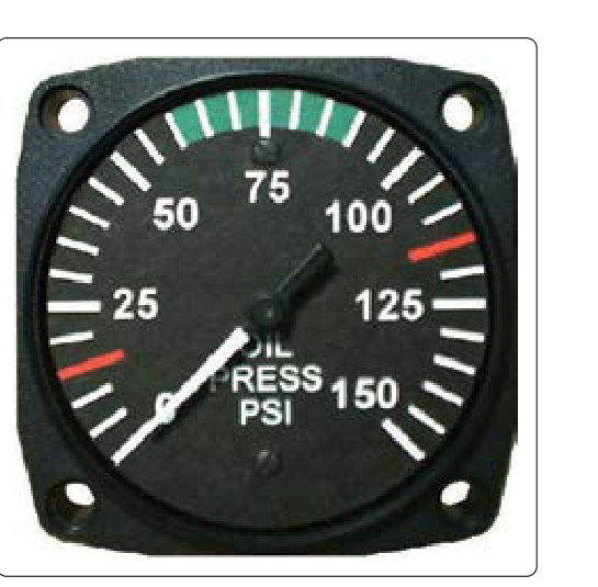
Engine oil pressure is one of the most vital parameters an aircraft engine monitor can display. A sudden drop in oil pressure can precede catastrophic engine failure within seconds or minutes, making the oil pressure gauge among the first instruments a pilot checks after engine start and one of the most vigilant to watch during flight. For the Aviation Maintenance Technician (AMT) working on powerplant systems, understanding exactly how oil pressure is sensed, transmitted, and displayed—and how to troubleshoot each type—is a core competency tested on the FAA Powerplant Knowledge Exam.
Two fundamentally different system architectures are used in certificated aircraft: the direct-reading Bourdon tube gauge, which connects the cockpit instrument directly to the oil system via a pressure line, and the remote-reading electrical system, which uses a pressure transmitter near the engine to send an electrical signal to a cockpit indicator. Each has distinct advantages, limitations, maintenance considerations, and failure modes.
The Bourdon Tube Gauge: How It Works
The Bourdon tube is one of the oldest and most reliable pressure-sensing mechanisms in engineering. A Bourdon tube is a curved, hollow, flattened metallic tube—typically made of brass or stainless steel—sealed at one end and open at the other to the pressure source. When oil pressure enters the open end, the tube tends to straighten out because the cross-sectional area of the flattened tube creates an unequal pressure force on the inner and outer walls. The higher the pressure, the more the tube tries to uncurl.
This mechanical movement is extremely small, so it is amplified through a series of linkages—typically a small sector gear meshing with a pinion gear—that rotate a pointer across a calibrated scale on the instrument face. The entire mechanism is housed within the instrument case mounted in the cockpit. Because there is no electrical component, the reading is instantaneous and requires no electrical power whatsoever.
In a direct-reading Bourdon tube installation, a small-diameter metal or armored tubing line runs from a fitting on the engine's oil pressure port all the way through the firewall and to the back of the cockpit gauge. This means raw engine oil, under full system pressure, is present inside a line that penetrates the cabin. The critical safety implication is clear: if that line or fitting fails anywhere between the engine and the cockpit, hot pressurized oil can spray into the cockpit or engine compartment—a potential fire and visibility hazard. For this reason, direct Bourdon tube oil pressure lines on certificated aircraft must be made of metal (not flexible rubber hose alone for the cabin-penetrating section) and must be properly secured to prevent chafing and vibration fatigue.
Advantages of the Bourdon Tube System
- Simplicity: No electrical wiring, transmitters, or power supply needed. Fewer components mean fewer potential failure points in the sensing and transmission portion of the system.
- Instantaneous response: The mechanical linkage responds to pressure changes in real time with no signal processing delay.
- No power dependency: The gauge reads correctly even with a total electrical failure, which is significant for engine-out or electrical emergency scenarios.
Disadvantages of the Bourdon Tube System
- Fire hazard potential: The pressurized oil line passing through the firewall is the primary safety concern, as noted above.
- Vibration sensitivity: Engine vibration transmitted through the oil line can cause pointer oscillation and accelerated wear of the mechanical linkage inside the instrument.
- Line length limitation: Running a pressurized oil line a long distance—as would be required in a twin-engine or turbine aircraft where the engine is far from the cockpit—is impractical and unsafe. This makes direct Bourdon tube systems essentially limited to small single-engine piston aircraft.
Remote-Reading Electrical Transmitter Systems: How They Work
In an electrical oil pressure indicating system, the pressurized oil line is terminated at a pressure transmitter mounted near the engine—usually on the engine itself or on the firewall in the engine compartment. No pressurized oil enters the cockpit. Instead, the transmitter converts mechanical pressure into an electrical signal that travels via standard aircraft wiring to a cockpit indicator.
The most common transmitter type used in general aviation piston aircraft is the variable-resistance (ratiometer or Bourdon-movement) transmitter. Inside the transmitter, the oil pressure acts on a Bourdon tube or diaphragm that moves a wiper arm across a resistance wire (a rheostat). As pressure increases, the resistance in the circuit changes, and the current flowing to the cockpit gauge changes proportionally. The cockpit indicator is a ratiometer or D'Arsonval movement galvanometer calibrated in PSI rather than electrical units, so the pilot reads oil pressure directly.
Some more sophisticated aircraft—particularly turbine-powered types—use pressure transducers that output a voltage or a 4–20 mA current loop signal, which is then processed by an electronic engine instrument system (such as an Engine Indication and Crew Alerting System, EICAS, or an Electronic Flight Instrument System display). These solid-state sensors have no moving parts and are highly accurate, but the underlying principle—converting pressure to an electrical signal—remains the same.
Advantages of Remote-Reading Systems
- No pressurized oil in the cockpit: Eliminating the oil pressure line through the firewall removes the fire and contamination risk associated with Bourdon tube direct-reading installations.
- Adaptable to any aircraft size: Electrical wiring can run any distance without the hazards of long pressurized fluid lines, making this system standard on multi-engine piston, turboprop, and jet aircraft.
- Reduced vibration effect on the indicator: The cockpit gauge is isolated from engine vibration; the transmitter absorbs it locally.
Disadvantages of Remote-Reading Systems
- Electrical dependency: Loss of electrical power means loss of indication. A failed bus or open circuit can give a falsely low or zero reading even when oil pressure is normal.
- More components: Transmitter, wiring, connectors, and the indicator are all potential failure points.
- Lag and damping: Some systems include a damping resistor or capacitor to smooth pointer oscillation, which can slightly delay indication of rapid pressure changes.
Why Oil Pressure Indication Matters
Engine lubrication oil serves to reduce friction, cool internal components, and in many engines, actuate variable-pitch propeller governors and hydraulic valve lifters. Normal operating oil pressure varies considerably by engine model—some reciprocating aircraft engines normally run in the range of roughly 30 to 60 PSI, while others operate normally in a 60 to 90 PSI range—so there is no single universal figure that applies to all reciprocating engines. The specific normal operating range, minimum, and maximum oil pressure limits are published in the aircraft's Pilot's Operating Handbook and the engine manufacturer's operating limitations (including the applicable Type Certificate Data Sheet)—these are the authoritative values for any given installation. Minimum oil pressure at idle and maximum pressure during cold starts are equally defined limits that the AMT must know.
If oil pressure drops below the minimum limit, an engine can suffer metal-to-metal contact within seconds. A slow pressure drop may indicate a developing oil leak, worn pump, or clogged filter. A sudden drop to zero almost certainly signals a catastrophic oil system failure. Conversely, oil pressure that is abnormally high—especially during cold weather starts before the oil warms and thins—can stress seals and gaskets. Recognizing these failure modes requires a correctly calibrated, accurately reading pressure system.
Key Numbers and Maintenance Rules
- Direct Bourdon tube oil pressure lines must be metal where they pass through the firewall, per standard airworthiness practice; flexible sections must be properly fire-sleeved and supported.
- After any maintenance involving the oil system or pressure transmitter, the AMT must run the engine and verify pressure indication comes up within 30 seconds (some manufacturers specify as little as 10–15 seconds at normal temperatures)—failure to see pressure within this window is cause to shut down immediately.
- Transmitter fittings must be sealed with the correct thread sealant (typically PTFE tape or approved pipe sealant) and torqued to specification; over-tightening can crack the transmitter body, under-tightening causes oil leaks.
- When troubleshooting a suspected inaccurate electrical gauge, a calibrated master pressure gauge is connected directly to the oil pressure port to establish actual system pressure, allowing comparison to the cockpit indication.
- A reading of zero PSI immediately after engine start—with the engine running—is an emergency condition requiring immediate shutdown; do not assume it is an instrument fault without verification.
Common Test Traps
- Confusing the two system types: The FAA exam may ask which system uses pressurized oil lines into the cockpit (Bourdon tube, direct-reading) versus which keeps all oil pressure contained at the engine (transmitter/electrical). Know the distinction cold.
- Assuming zero indication always means zero pressure: In an electrical system, an open circuit, a failed transmitter, or a blown fuse can produce a zero or pegged reading with no actual oil pressure problem. Always use a master gauge to verify.
- Ignoring the fire risk of direct Bourdon tube lines: Exam questions on airworthiness often test whether a technician knows that an oil pressure line penetrating the cockpit must be metal, not rubber hose.
- Misidentifying the sensing element: Both system types can use a Bourdon tube as the sensing element—the difference is whether the tube's mechanical movement directly drives a pointer (direct-reading) or moves a rheostat wiper to produce an electrical signal (transmitter). The tube itself does not define the system type.
- Neglecting damping: Some AMTs overlook the small restrictor fitting or damping orifice installed in the oil pressure port. This fitting dampens pointer flutter; if removed or clogged, the gauge either oscillates wildly or reads zero. The exam may present this as a troubleshooting scenario.