Among all the parameters an aviation mechanic or pilot monitors on a turbine engine, Turbine Inlet Temperature (TIT) stands at the top of the list for criticality. The temperature of combustion gases entering the turbine section is the single most important thermal limit of any gas turbine engine. Exceed that limit — even briefly — and the consequences range from accelerated creep and oxidation of turbine blades to catastrophic structural failure. Understanding how TIT is measured, displayed, and protected is fundamental knowledge for any Aviation Maintenance Technician (AMT) working on powerplant systems.
TIT is sometimes used interchangeably with related terms such as Exhaust Gas Temperature (EGT), Turbine Gas Temperature (TGT), and Interstage Turbine Temperature (ITT), though each refers to a specific measurement point within the engine. True TIT is measured between the combustor exit and the leading edge of the first-stage turbine nozzle guide vanes — the hottest location in the entire gas path. Because placing sensors at that exact point is extremely challenging, most engines measure temperature at a closely related location and refer to the reading under a slightly different acronym. The principles, however, are the same.
Why Turbine Temperature Is So Critical
The first-stage turbine blades and nozzle guide vanes operate in an environment that would melt ordinary metal. Temperatures at the turbine inlet of a modern high-performance turbine engine can exceed 2,500°F (roughly 1,370°C), which approaches or can exceed the melting point of some nickel-based superalloys used to make those components. These parts survive only because of sophisticated internal cooling channels that circulate compressor bleed air through and around the blade material, and because of thermal barrier coatings applied to their surfaces.
Because the turbine section's thermal tolerance is so narrow, TIT is the parameter that most directly determines the engine's power output ceiling and its service life. The FAA Aviation Maintenance Handbook (FAA-H-8083-32) notes that turbine section temperature limits must be strictly observed; even a moderate overtemperature event must be logged, investigated, and may require immediate inspection or removal of affected components. Operating consistently near or above temperature limits drastically shortens the hot-section inspection interval and accelerates the need for expensive turbine blade replacement.
How TIT Is Measured
The core sensing technology for TIT relies on thermocouple probes. A thermocouple works on the Seebeck effect: when two dissimilar metals are joined at one end (the hot junction) and a temperature difference exists between that junction and the other end (the cold or reference junction), a small electromotive force (EMF) — a voltage — is produced. The magnitude of that voltage is proportional to the temperature difference between the two junctions. The cockpit instrument reads this voltage and translates it into a temperature indication, typically in degrees Celsius or degrees Fahrenheit depending on the aircraft type.
For TIT measurement, the thermocouple materials most commonly used in turbine engines are chromel-alumel (chrome-nickel alloy paired with an aluminum-nickel alloy) and, for higher-temperature applications, platinum-rhodium alloys. Chromel-alumel thermocouples are accurate and durable up to approximately 2,300°F (1,260°C). At higher temperature ranges, platinum-rhodium thermocouples offer greater stability, though they are significantly more expensive.
Probe Placement and Averaging
Because temperatures are not perfectly uniform around the circumference of a turbine engine's annular combustor exit, a single thermocouple probe would give an unrepresentative reading. For this reason, most engines use a harness of multiple probes — often called a thermocouple rake or TIT harness — that samples the gas stream at several points around the engine's circumference. The individual probe outputs are connected in parallel, which effectively averages the readings across the measurement plane. This averaging approach gives the instrument a reading that better represents the actual thermal load on the turbine section as a whole, while also providing redundancy against individual probe failure.
The probes themselves are mounted in the engine diffuser case or combustor exit area and extend into the gas path. They must be robust enough to withstand not only extreme temperatures but also high-velocity gas flow, vibration, and the erosive effects of combustion byproducts. Stainless steel or Inconel sheaths protect the thermocouple wires while allowing sufficient thermal contact with the gas stream. Each probe is wired with extension leads made of the same thermocouple alloy (not ordinary copper wire) to prevent introducing additional EMF errors in the circuit.
The TIT Indicating System
The TIT indicating system on a turbine-powered aircraft is a self-powered electrical circuit — it generates its own electricity from the temperature difference across the thermocouple and requires no external power source to function. This is an important distinction from many other aircraft instruments, because it means TIT indication remains available even with a total electrical system failure. The indicating instrument, often called a pyrometer, is essentially a sensitive galvanometer calibrated in temperature units. It measures the microvolts or millivolts generated by the thermocouple harness and displays the corresponding temperature.
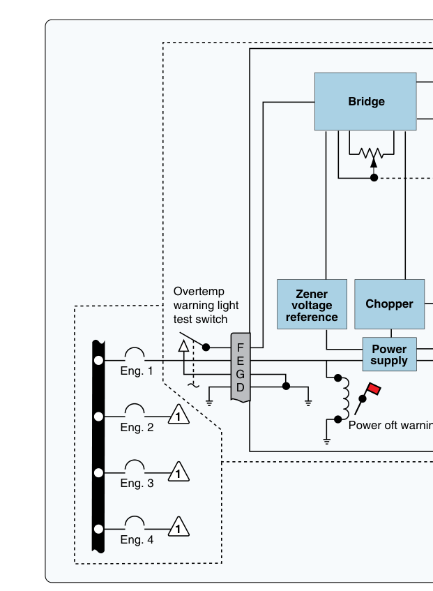
Modern turbine aircraft may display TIT on a traditional analog gauge (a needle sweeping across a dial face), a digital readout, or as part of an integrated Engine Indicating and Crew Alerting System (EICAS) or Electronic Centralized Aircraft Monitor (ECAM) display. In any format, the red line — the never-exceed temperature limit — is clearly marked. Many systems also incorporate a separate overtemperature warning light or aural alert that activates if TIT approaches or exceeds the limit.
Key Numbers and Rules
- Temperature limits are engine-specific: There is no single universal TIT limit. Each engine model's Type Certificate Data Sheet and the engine manufacturer's maintenance manual specify the maximum continuous TIT, the maximum transient TIT (a higher value allowable for a short duration, such as 5 seconds during starting), and the maximum starting temperature limit. The AMT must reference the correct manual for the specific engine being maintained.
- Overtemperature inspections: Per FAA guidance and engine manufacturer procedures, any TIT exceedance — regardless of duration — must be recorded in the engine logbook and typically requires a hot-section inspection or borescope inspection before further flight. Some manufacturers require engine removal after certain thresholds are exceeded.
- Thermocouple resistance check: The FAA Powerplant Handbook (FAA-H-8083-32) indicates that the resistance of the thermocouple circuit is critical. An ammeter-type TIT indicator reads a current that is proportional to the EMF produced; the circuit resistance affects calibration accuracy. Most systems have a specified total circuit resistance; if resistance drifts due to a corroded or broken probe, the reading will be erroneous.
- Lead wire material: Extension wires in a thermocouple circuit must be made of the same metals as the thermocouple itself, or of approved thermocouple extension alloys. Using standard copper wire introduces a spurious junction and produces significant measurement error.
- Self-powered circuit: The TIT system generates its own EMF and does not require aircraft electrical bus power for the basic temperature reading. This is a common test and practical examination question.
Common Causes of Erroneous TIT Readings
Accurate TIT indication is only useful if the system is functioning correctly. An AMT troubleshooting a suspicious TIT reading should consider several possible failure modes. A broken or shorted thermocouple probe in a parallel harness will cause the average to shift, producing a false low reading — dangerous because the pilot may think TIT is acceptable when it is not. A broken lead wire creating an open circuit in a series-parallel harness may cause the indicator to deflect full-scale high or read zero, depending on the circuit design. Improper lead wire material (copper substituted for thermocouple alloy) creates an erroneous EMF at the junction between different metals. Moisture or contamination in connectors can create leakage paths that alter circuit resistance and shift readings. The AMT should use a calibrated millivolt source (a thermocouple calibrator) to verify system accuracy from the probe harness connection point to the cockpit indicator.
TIT vs. EGT, ITT, and TGT
Students and technicians frequently encounter confusion between TIT and related temperature measurements. EGT (Exhaust Gas Temperature) is measured in the exhaust section, well downstream of the turbine stages — it is a lower temperature than true TIT and is the most common indicator on turboprop and many turbojet engines because the measurement point is more accessible. ITT (Interstage Turbine Temperature) is measured between turbine stages on multi-stage turbines and is used on many turboshaft and turboprop engines, including many business aviation powerplants. TGT (Turbine Gas Temperature) is another term for measurement at or near the turbine exit. All of these systems use thermocouple technology and follow the same operating principles as true TIT, but the specific measurement location — and therefore the actual temperature values — differ. The relationship between these values and the true turbine inlet condition is accounted for in the engine's certified operating limits.
Common Test Traps
- Confusing self-powered vs. externally powered: The TIT/EGT thermocouple circuit is self-generating — it does not require battery or bus power for the basic reading. Confusing this with externally powered instruments is a frequent exam error.
- Wrong lead wire material: Many questions test whether the student knows that thermocouple extension leads must use the same alloy as the thermocouple. Substituting copper wire introduces an erroneous thermocouple junction and corrupts the reading.
- Broken probe in parallel harness reads low, not high: An open probe in a parallel-connected harness removes one reading from the average, typically causing the indicated temperature to read lower than actual — a dangerous failure mode that is easy to miss.
- Overtemperature always requires documentation: Any TIT exceedance, however brief, requires a logbook entry and inspection per the engine manufacturer's instructions. Students sometimes think a very brief overtemperature can simply be ignored.
- TIT is not the same as EGT: Questions may describe a system and ask which parameter is being measured. True TIT is at the turbine inlet (combustor exit); EGT is measured in the exhaust section at a much lower temperature. Knowing the measurement location is essential.