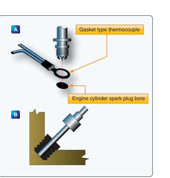
Of all the temperatures an aircraft engine generates, the one that matters most to long-term engine health is the temperature at the cylinder head. The combustion event happens inside the cylinder, and the head — the aluminum or steel casting that seals the top of the cylinder — absorbs an enormous amount of that heat. If that heat is not properly managed, the metal weakens, valves burn, and catastrophic engine failure follows. The Cylinder Head Temperature (CHT) thermocouple system gives pilots and mechanics a continuous, direct window into the thermal condition of the engine's hardest-working components. Understanding how these systems work, why they matter, and how to interpret their readings is essential knowledge for any AMT Powerplant technician.
CHT instrumentation is required equipment on many certificated aircraft and is universally recommended even where not legally mandated. The FAA addresses CHT systems in the context of engine instrument requirements and powerplant monitoring throughout the Aviation Maintenance Handbook — Powerplant (FAA-H-8083-32) and related powerplant guidance. Mastering the underlying physics and practical maintenance considerations will prepare you for both the written knowledge test and real-world shop work.
The Physics of Thermocouples
A thermocouple is a temperature-sensing device that exploits the Seebeck effect: when two dissimilar metals are joined at one end (the hot junction) and the other ends are connected to a measuring circuit (the cold junction or reference junction), a small electromotive force (EMF) — measured in millivolts — is generated. The magnitude of this voltage is directly proportional to the temperature difference between the hot junction and the cold junction. Because the relationship between voltage and temperature is well-characterized for each metal pair, the instrument can convert the measured EMF into a precise temperature reading.
For CHT applications on aircraft piston engines, the most commonly used thermocouple material pairs are chromel-alumel (Type K) and iron-constantan (Type J). Chromel-alumel is particularly prevalent because it handles the high temperatures typical of aircraft engine cylinder heads — often ranging from ambient up to and beyond 500°F (260°C) — and produces a relatively linear output across that range. The specific material pair used in a given aircraft must be matched precisely to the indicator; mixing thermocouple types with mismatched instruments produces inaccurate readings and is a common maintenance error to avoid.
System Components
The Hot Junction — Sensor at the Cylinder
The hot junction is physically located at the cylinder head itself. There are two common installation methods:
- Bayonet-type probe: A spring-loaded probe is inserted into a boss machined into the cylinder head, typically near the hottest region — often between the exhaust valve and the spark plug. The spring tension keeps the probe tip in firm contact with the metal. This design is easy to install and remove during routine maintenance.
- Gasket-type sensor: A flat thermocouple element is sandwiched under a spark plug, placing the junction directly in the metal at the plug boss. This design offers excellent thermal contact but requires removing the spark plug for sensor replacement.
Both designs are intentionally placed as close as possible to the exhaust valve seat, because that area runs the hottest on a typical four-stroke aircraft engine. The exhaust valve is cooled only by contact with the seat during the brief moment it closes; combustion gases rush past it during the exhaust stroke, making it the most temperature-stressed component in the assembly.
Extension Leads and Wiring
A critical and often overlooked aspect of thermocouple systems is that the lead wires from the hot junction to the instrument must be made of the same thermocouple alloy as the sensor itself, or of a certified thermocouple extension wire with equivalent thermoelectric properties. If ordinary copper wire is substituted — even for a short run — an unintended secondary thermocouple junction is created at the point of transition, introducing a measurement error. The FAA maintenance handbooks are explicit that thermocouple circuits must use matched extension wire throughout.
Thermocouple leads are color-coded by the manufacturer to prevent mix-ups, but the color convention used varies by installation and is not universal across aviation thermocouple systems. Technicians must always verify polarity against the aircraft or component manufacturer's wiring diagram during installation, because reversing the leads causes the instrument to deflect in the wrong direction, reading lower as temperature rises — a potentially dangerous condition that could mask an overheat.
The Cold Junction and the Indicator
The instrument itself contains the cold junction. Modern CHT gauges are typically self-powered — they require no external power supply because the thermocouple generates its own EMF. This is an important distinction from resistance-based temperature sensors (like those used in some oil temperature systems), which require an excitation voltage. Because the CHT indicator relies solely on the thermocouple's EMF, a broken or disconnected lead will cause the indicator to drop to the lowest reading, not to read a falsely high temperature. This fail-safe behavior is important: a pegged-low reading during engine operation should immediately raise suspicion of a wiring fault.
The cold junction compensation is built into the indicator design. Because the EMF output reflects only the difference between hot and cold junction temperatures, the instrument must account for variations in ambient cockpit temperature at the reference junction. Quality indicators include a bimetallic compensator that adjusts the calibration automatically as cockpit temperature changes, keeping the reading accurate across a range of ambient conditions.
Multi-Cylinder Monitoring Systems
Many aircraft with multi-cylinder engines are equipped with a multi-probe CHT system that monitors every cylinder individually, often combined with exhaust gas temperature (EGT) probes in an engine monitor or engine data management (EDM) unit. These systems scan each thermocouple in sequence and display individual cylinder temperatures, allowing the pilot and mechanic to identify a single cylinder that is running abnormally hot or cool. In older aircraft with a single CHT gauge, only one cylinder is monitored — typically the one identified by the engine manufacturer as the hottest-running cylinder under normal conditions. Technicians must consult the aircraft's Type Certificate Data Sheet and the engine manufacturer's data to confirm which cylinder the probe is installed on, and whether that installation complies with the approved configuration.
Why CHT Monitoring Matters
CHT is the single most direct indicator of the health of the combustion process. Elevated CHT is associated with several dangerous conditions:
- Detonation: Abnormal combustion in which the fuel-air mixture ignites spontaneously ahead of the flame front, producing a rapid pressure spike. Detonation dramatically increases heat load on the cylinder head. Sustained detonation will crack cylinder heads, burn pistons, and destroy engines quickly. High CHT is often the first cockpit indication of detonation.
- Pre-ignition: The mixture ignites before the spark plug fires, usually from a hot spot inside the combustion chamber such as a carbon deposit or an overheated exhaust valve. Pre-ignition is even more destructive than detonation and can burn a hole through a piston in seconds. CHT climbs rapidly and uncontrollably when pre-ignition is occurring.
- Lean mixture conditions: Operating too lean of peak (especially at high power settings) increases CHT, because less fuel means less evaporative cooling in the cylinder. Understanding the relationship between mixture setting and CHT is critical for proper engine management.
- Cooling system failures: Blockage of cylinder fins, damaged baffling, or cowl flap malfunctions all reduce airflow over the cylinders and cause CHT to rise.
Key Numbers and Limits
- Maximum CHT limits vary by engine make and model, but many air-cooled aircraft engines have a red-line CHT limit in the range of 400°F to 500°F (204°C to 260°C). Always reference the specific engine's Type Certificate or the Pilot's Operating Handbook for the applicable limit.
- For best engine longevity, many engine manufacturers recommend keeping CHT below 380°F (193°C) during cruise, even though the red line may be higher.
- During climb — the most thermally demanding phase of flight because power is high and airspeed (and thus cooling airflow) is relatively low — monitoring CHT is especially important. Enrichening the mixture and/or increasing airspeed can reduce CHT rapidly.
- A sudden, unexplained CHT drop on one cylinder can indicate a failed injector nozzle (in fuel-injected engines) causing that cylinder to run lean or stop firing, or a broken thermocouple wire.
- Thermocouple systems are self-powered; no aircraft bus voltage is required for basic CHT indication (though digital EDM systems require power for their display electronics).
Maintenance Considerations
During annual inspections and engine overhauls, technicians should inspect CHT probes and leads carefully. Look for cracked or frayed insulation on extension leads, corroded or loose connections at the instrument and at the cylinder boss, and physical damage to bayonet probes from overtorque or vibration. Bayonet probes rely on spring tension for good thermal contact — a weak or collapsed spring produces artificially low readings. Gasket-type probes should be checked for cracks in the element itself. Any time a cylinder is removed or a spark plug is changed on a gasket-type installation, the thermocouple element must be inspected and replaced if damaged.
When returning a thermocouple system to service, a functional check should confirm that the indicator responds in the correct direction as the engine warms up. If the reading does not rise with engine temperature, suspect reversed polarity, a broken lead, or a failed indicator cold-junction compensator.
Common Test Traps
- Mixing thermocouple types: Using a Type J sensor with a Type K indicator (or vice versa) produces inaccurate readings. The test may present scenarios where the wrong extension wire is installed; recognize this as a calibration error source.
- Reversed leads read low, not high: A reversed thermocouple installation causes the indicator to read lower as temperature rises — the opposite of what many students expect. A pegged-low CHT on an otherwise normal engine is a red flag for wiring reversal or an open circuit.
- Self-powered vs. externally powered: CHT thermocouple gauges do not require aircraft electrical power for the sensing function. The FAA written test sometimes tests whether students know the difference between thermocouple-based instruments and resistance-type sensors.
- Hottest cylinder location: On a single-probe installation, the probe goes on the cylinder the manufacturer identifies as hottest — not necessarily any particular cylinder number. Do not assume it is always the same cylinder across different engine models.
- CHT vs. EGT probes are not interchangeable: EGT probes are located in the exhaust stack, not the cylinder head, and measure exhaust gas temperature — a different parameter using a similar but separately calibrated thermocouple. Installing an EGT probe in a CHT boss, or vice versa, produces incorrect readings and is an airworthiness defect.