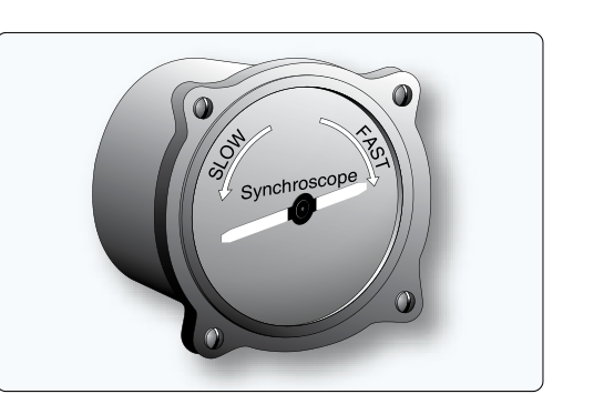
On a multi-engine aircraft, even small differences in propeller rotational speed between engines can produce an annoying — and structurally relevant — beat frequency that vibrates through the airframe. To eliminate this phenomenon, the RPM of all engines must be precisely synchronized. The synchroscope is the dedicated instrument designed to make that synchronization visible, giving the pilot or flight engineer a clear, real-time indication of which engine is running faster or slower relative to a reference engine. Understanding how a synchroscope works, how to interpret its display, and how to act on its readings is fundamental knowledge for any Aviation Maintenance Technician (AMT) working on multi-engine powerplant systems.
This article covers the operating principles of the synchroscope, how it integrates with tachometer generator systems, the correct maintenance and operational procedures, and the exam-critical details you need to know for the FAA AMT Powerplant knowledge test.
The Beat Frequency Problem
When two propellers spin at slightly different RPM, their individual pressure pulses combine in the cabin air and through the airframe structure. The difference in frequency between the two engines creates a beat frequency — perceived as a rhythmic throb or wah-wah sound. Even a difference of just a few RPM is enough to produce a noticeable beat. The faster the difference, the faster the beat. Synchronizing RPM eliminates the beat frequency entirely, producing a much smoother and quieter cabin environment and reducing cyclic stress loads on the airframe. The synchroscope is the instrument that makes precise manual synchronization possible.
How the Synchroscope Works
A synchroscope is an electrically driven instrument that compares the rotational speed of one engine — called the slave engine — against another engine designated as the master engine. The instrument displays the relative speed difference, not absolute RPM. Because it shows only the difference, it complements the tachometer rather than replacing it; the pilot first sets desired RPM on all engines using the tachometers, then fine-tunes with the synchroscope.
Electrical Signal Generation
Each engine drives a small AC generator called a tachometer generator (tach generator). The tach generator produces an AC voltage whose frequency is directly proportional to engine RPM. Depending on the specific installation, a tach generator may produce a single-phase or three-phase AC output; in either case, the frequency of that output rises and falls in lock-step with crankshaft (or propeller shaft) speed. This frequency-coded signal is the fundamental electrical input to the synchroscope system.
The Synchroscope Motor and Pointer
Inside the synchroscope instrument, a small synchronous motor is connected so that it receives the output signal from both the master and slave engine tach generators simultaneously. The motor is wound and connected in such a way that it responds to the difference in frequency between the two signals. When the two engines are at exactly the same RPM, the two AC frequencies are identical, the motor sees a net difference of zero, and the synchroscope pointer (or disk) remains stationary. This stationary position is the target condition — perfect synchronization.
When the slave engine runs faster than the master, the frequency difference drives the motor to rotate in one direction. In the commonly taught convention, the synchroscope pointer rotates clockwise when the slave engine is running fast, and counterclockwise when the slave engine is running slow — but the actual rotation direction depends on the specific aircraft's wiring and instrument installation, so technicians should always confirm the direction convention against the applicable aircraft maintenance manual rather than assume it is universal. The speed of pointer rotation indicates the magnitude of the RPM difference: a slowly creeping pointer means the engines are nearly synchronized; a rapidly spinning pointer means there is a large speed discrepancy.
Reading the Synchroscope in Practice
The synchroscope indicator face typically depicts a small airplane symbol or a simple arrow. The pilot or technician observes the direction and rate of rotation:
- Pointer stationary: Slave and master engines are synchronized — RPM is matched.
- Pointer rotating clockwise (FAST): The slave engine is running faster than the master. Reduce slave engine RPM (or increase master engine RPM) to slow or stop the rotation.
- Pointer rotating counterclockwise (SLOW): The slave engine is running slower than the master. Increase slave engine RPM (or reduce master engine RPM).
- Pointer rotating rapidly: There is a large RPM difference between engines. First use tachometers to get both engines close to the desired RPM, then use the synchroscope for fine-tuning.
Proper operating procedure is to designate one engine as the reference (master), as specified by the aircraft manufacturer's electrical wiring and AFM/POH, and adjust all other engines relative to that master. The synchroscope then displays each slave engine's condition relative to the master.
System Components and Maintenance Considerations
The synchroscope system on a typical twin includes the following components that an AMT must be familiar with:
- Tachometer generators: Engine-driven AC generators, one per engine. They must be correctly driven at the proper gear ratio from the engine to produce an accurate frequency signal. Worn or improperly mounted tach generators introduce inaccurate readings.
- Wiring and connectors: Signal wiring between the tach generators and the synchroscope instrument must be secure and free from shorts, opens, or chafing. A damaged wire can cause erratic pointer behavior or a continuously rotating pointer even when engines are synchronized.
- Synchroscope instrument: The instrument itself contains the synchronous motor, indicator mechanism, and usually a damping device to prevent excessive pointer oscillation. Instrument failure is indicated by a pointer that spins continuously or fails to respond when engine RPM is clearly different.
- Propeller governor system: While not part of the synchroscope itself, the propeller governors on constant-speed propellers must be functioning correctly. The synchroscope can only display a difference; correction is made through the propeller RPM controls (condition levers or prop levers on turboprops, or throttle/prop controls on reciprocating engines).
Troubleshooting Synchroscope Malfunctions
When a synchroscope gives suspect readings, an AMT should verify correct tach generator output frequency using appropriate test equipment before condemning the synchroscope instrument itself. If one tach generator produces an incorrect frequency due to a faulty internal permanent magnet or worn drive coupling, the synchroscope will always indicate a difference even when engines are at the same RPM. Conversely, an open circuit in one tach generator lead will cause the pointer to spin continuously because the motor is receiving a signal from only one engine. Always check the tach generator outputs at the instrument connector before replacing the instrument.
Relationship to Propeller Synchronizers and Synchrophasers
The synchroscope is a manual synchronization aid — it requires the pilot to observe the display and manually adjust the propeller RPM controls. More advanced systems automate this process:
- Propeller synchronizer: An automatic electronic system that compares tach generator outputs and makes small automatic adjustments to one engine's propeller governor to maintain matched RPM without pilot input. The synchroscope may still be installed as a backup or monitoring display.
- Propeller synchrophasor: A more sophisticated automatic system that not only synchronizes RPM but also controls the phase angle between the propeller blades of different engines. By locking the blades at a specific relative angular position, the synchrophasor can further reduce cabin noise beyond what simple RPM synchronization achieves.
Understanding the distinction between these three levels of synchronization — manual (synchroscope), automatic RPM matching (synchronizer), and automatic phase matching (synchrophasor) — is directly tested on the FAA AMT Powerplant exam.
Key Numbers and Rules
- A synchroscope pointer stationary = synchronized RPM between master and slave engines.
- Pointer rotating clockwise = slave engine FAST (above master RPM) in the commonly taught convention, though actual direction is installation-specific.
- Pointer rotating counterclockwise = slave engine SLOW (below master RPM) in the commonly taught convention, though actual direction is installation-specific.
- The rate of rotation of the pointer indicates the magnitude of RPM difference — faster spin means greater discrepancy.
- Tach generator output frequency is proportional to RPM; it is this frequency difference that drives the synchroscope motor.
- The synchroscope shows only relative speed, not absolute RPM; always use primary tachometers to set the target RPM first.
- An open circuit in a tach generator lead will cause the pointer to rotate continuously — a common exam scenario.
Common Test Traps
- Confusing direction convention: Clockwise means the slave is FAST, counterclockwise means SLOW, per the commonly taught convention — but always verify against the specific aircraft's maintenance documentation, since the exact direction can be installation-specific. The exam may try to reverse this or present it ambiguously. Remember: the direction tells you what the slave is doing relative to the master.
- Assuming the synchroscope replaces the tachometer: It does not. It shows only the RPM difference. You must set approximate RPM with the tachometer first, then fine-tune with the synchroscope.
- Misidentifying a continuously rotating pointer: A pointer that never stops does NOT necessarily mean the engines are wildly out of sync. An open tach generator circuit will produce the same symptom. Always check the electrical system before assuming a large RPM discrepancy.
- Confusing synchroscope with synchronizer: A synchroscope is a manual indication instrument only; it makes no automatic corrections. A propeller synchronizer makes automatic corrections. A synchrophasor additionally controls blade phase angle. Do not mix up these three systems.
- Overlooking the master engine designation: The synchroscope always compares a slave to a master. Changing which engine is master changes the meaning of the display. Maintenance procedures and cockpit placards will specify which engine serves as master.