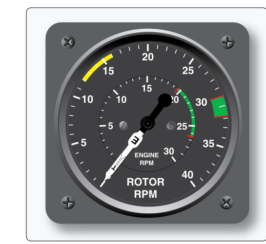
The tachometer is one of the most fundamental engine instruments in any aircraft. Whether you are troubleshooting a piston trainer or inspecting a turbine powerplant, you need to know precisely how fast the engine is turning. That deceptively simple number — revolutions per minute, or RPM — tells the pilot and mechanic a great deal about power output, propeller loading, and engine health. For the AMT powerplant candidate, understanding the three major categories of tachometer — mechanical, electrical, and electronic — means knowing not just how each one works, but how each one can fail, how accuracy is verified, and why the FAA cares about calibration and serviceability.
This article walks through all three system types in depth, explains the physics and components behind each, and closes with the testable details most likely to appear on the FAA AMT Powerplant Knowledge Test.
Why RPM Measurement Matters
Engine RPM is directly tied to power output in a reciprocating engine. Pilots set power by reference to the tachometer (and manifold pressure gauge on constant-speed installations). Mechanics use RPM readings during run-ups to evaluate magneto drop, carburetor heat effectiveness, and propeller governing. An inaccurate or malfunctioning tachometer can mask an over-revving condition, cause an improper power setting, or — in the worst case — allow an engine to operate beyond its red-line limit, risking catastrophic mechanical failure. Under 14 CFR 91.205, a tachometer for each engine is required equipment for powered civil aircraft, making its airworthiness a legal requirement, not merely a convenience.
Mechanical Tachometers
The oldest and simplest tachometer design uses a direct mechanical connection between the engine and the indicator. A flexible steel drive cable — similar in construction to a speedometer cable on an automobile — connects a rotating gear on the engine accessory case to the indicator head in the instrument panel. The cable is housed inside a flexible outer sheath, allowing it to route around bulkheads and through tight spaces without binding.
Inside the indicator, the rotating cable drives a small permanent magnet that spins inside an aluminum drag cup. As the magnet rotates, it induces eddy currents in the surrounding aluminum cup, and those eddy currents generate a magnetic field that tries to follow the spinning magnet. A calibrated hairspring opposes the drag cup's rotation, and the cup deflects to a position where spring tension balances magnetic drag. That deflection moves a pointer across the RPM scale. This arrangement is called a magnetic drag or eddy-current tachometer, and it is the same basic principle used in most automobile speedometers of the pre-digital era.
The drive ratio between the engine gear and the instrument is carefully chosen so that the indicator reads in crankshaft RPM even though the drive may be taken from a camshaft or accessory gear turning at a different speed. That ratio is engraved or marked on many tachometer heads and must be matched correctly when a replacement indicator is installed.
Mechanical Tachometer Failure Modes
Because the mechanical tachometer has moving parts exposed to vibration and temperature extremes, it has several characteristic failure modes. A broken or kinked drive cable is the most common problem; it typically produces erratic needle fluctuation or a complete zero reading. A seized cable can cause the needle to stick or, in severe cases, can damage the instrument head gears. Lubrication of the cable is required at specified intervals — too little causes wear and noise, too much can cause the grease to migrate into the indicator and dampen the drag cup. Always consult the manufacturer's maintenance manual for the correct lubricant type and interval.
Electrical Tachometers
Larger or more complex aircraft — particularly those where the cockpit is far from the engine, or where running a flexible cable is impractical — use electrical tachometer systems. A common type relies on a small AC generator, often called a tachometer generator or tach generator, mounted on the engine accessory case. Depending on design, these generators may be single-phase, two-phase, or three-phase. As the engine turns, the tach generator produces an alternating current whose frequency is directly proportional to engine RPM. There is no need to measure voltage amplitude; it is the frequency that carries the RPM information.
That AC signal is sent over lightweight electrical wiring to a synchronous motor inside the cockpit indicator. The synchronous motor turns at a speed directly determined by the incoming frequency — it literally locks onto and follows the frequency of the generator signal. The synchronous motor then drives the same type of magnetic drag mechanism described for mechanical systems, moving the pointer across the scale. Because the electrical signal replaces the mechanical cable, multiple indicators can be connected to a single generator, making it straightforward to provide both pilot and copilot with independent RPM readouts from one source.
The tach generator is a precision component, and its phase configuration is chosen by the manufacturer to provide smooth, ripple-free torque on the synchronous motor at all RPM values, including at idle where the generator frequency is low.
Electrical Tachometer Failure Modes
Because electrical tachometers depend on a generator and a motor, their failure modes differ from mechanical systems. An open circuit — a broken wire or failed connector — will cause the indicator to read zero or drop to zero in flight. A short circuit may cause erratic readings. The tach generator itself can fail due to bearing wear, winding degradation, or corrosion of the slip rings (on designs that use them). One important diagnostic point: if the electrical tachometer reads zero but the engine is clearly running, suspect an electrical fault rather than an actual engine problem. Conversely, the mechanical tachometer will simply stop or fluctuate if the drive cable breaks, giving a similar symptom but from a completely different cause.
Electronic (Digital) Tachometers
Modern aircraft increasingly use electronic tachometer systems that replace both the mechanical cable and the tach generator with solid-state sensors and digital processing. The most common sensor types are the magnetic pickup (also called a reluctance pickup) and the optical sensor.
A magnetic pickup is a passive sensor consisting of a permanent magnet wound with a fine wire coil. It is mounted close to a ferromagnetic gear or ring attached to the engine crankshaft or flywheel. As each gear tooth passes the pickup, it temporarily increases the magnetic flux through the coil, inducing a small voltage pulse. The electronic module counts these pulses over a precise time interval and calculates RPM based on the known number of teeth on the reference gear. This pulse-counting method is inherently accurate and immune to the amplitude variations that would affect a simple voltage-based system.
Optical sensors use an infrared LED and photodetector aimed at a toothed wheel or a reflective strip on a rotating component. Each interruption or reflection generates a pulse, and the same counting logic applies. Optical sensors are particularly useful in environments where electromagnetic interference would degrade a magnetic pickup signal, though they require a clean optical path free of oil contamination.
The electronic processing module converts the pulse train to a digital RPM value, which drives either a digital display or, through a servo motor, a conventional-looking analog needle. Many modern engine monitoring systems (EMS) integrate the tachometer function with other parameters — cylinder head temperature, exhaust gas temperature, oil pressure — all processed and displayed on a single multifunction display.
Electronic Tachometer Failure Modes
Electronic systems are highly reliable but not infallible. Magnetic pickups can fail if the air gap between the sensor and the gear teeth is incorrect — too large a gap reduces signal amplitude below the detection threshold, causing intermittent or zero readings. Metal debris accumulating on the pickup face (it is magnetic, after all) can bridge the gap and cause erratic output. Optical sensors fail if oil or contamination coats the optical faces. Most electronic EMS units have built-in self-test routines and will display a fault code or flag an invalid reading, providing the pilot and mechanic with a diagnostic clue unavailable in older systems.
Key Numbers and Rules
- Tachometer color coding: The green arc indicates the normal operating RPM range; the red line marks the maximum allowable RPM. Yellow arcs, if present, indicate caution ranges (often found on radial engines). These markings are established per the aircraft's type certification basis (e.g., 14 CFR Part 23 or Part 25 airworthiness standards, as applicable to the specific aircraft category) and are documented in the Type Certificate Data Sheet and the Aircraft Flight Manual/POH.
- Required calibration check: Tachometer accuracy is verified at annual inspection and after any repair. There is no single FAA-wide tolerance figure for tachometer accuracy; the applicable tolerance is defined by the specific instrument's TSO or the manufacturer's specifications. Always check the applicable ICA (Instructions for Continued Airworthiness).
- Drive cable replacement: Mechanical tachometer cables should be inspected for kinks, fraying, and proper lubrication. A broken cable must be replaced, not spliced.
- Tach generator drive ratio: When replacing an electrical tachometer indicator, the replacement must have the same drive ratio as the original. Mismatched ratios cause systematic over- or under-reading across the entire RPM range.
- Magnetic pickup gap: The air gap is specified by the manufacturer's maintenance manual or ICA and varies by installation and design — always consult the applicable manual for the correct value. Set the gap with a non-magnetic feeler gauge to avoid magnetizing the gauge blade.
- Turbine engines: Gas turbine tachometers often read in percent of maximum RPM (% RPM) rather than absolute RPM values, because turbine design speed is the meaningful reference parameter. Both N1 (fan/compressor) and N2 (power turbine) speeds may be indicated separately.
Common Test Traps
- Confusing zero reading causes: A zero tachometer reading can result from a broken mechanical cable, an open circuit in an electrical system, or a failed electronic sensor — all different causes with different fixes. The test may present a symptom and ask you to identify the most likely cause given the system type described.
- Drive ratio mismatch: Many candidates forget that an electrical tachometer indicator has a built-in drive ratio matched to the tach generator. Installing the wrong indicator part number causes a systematic RPM error, not just an occasional glitch. This is a common maintenance error the FAA tests directly.
- Turbine percent RPM: Students accustomed to piston tachometers sometimes misidentify a turbine tachometer reading. Remember that on turbine engines, the gauge typically reads in percent RPM, with 100% corresponding to the engine's rated design speed rather than a universal RPM value — the exact scale range is specific to the engine model and is not a fixed FAA-wide figure.
- Magnetic pickup gap tool: Always use a non-magnetic feeler gauge when setting pickup gap. Using a standard steel feeler gauge can magnetize it, altering the gap measurement and causing a faulty installation.
- Eddy-current principle: The FAA frequently tests the operating principle of mechanical tachometers. Know that the pointer deflection results from eddy currents induced in the drag cup by the rotating permanent magnet, balanced by a calibrated hairspring — not a direct gear drive to the pointer.