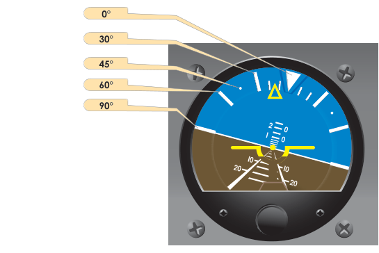
Of all the instruments in the cockpit, the attitude indicator — sometimes called the artificial horizon — is the one instrument pilots trust most when they cannot see the real horizon. During instrument meteorological conditions (IMC), it provides an immediate, intuitive picture of where the aircraft's nose and wings are relative to the earth, allowing precise aircraft control without any visual reference to the outside world. Understanding how the attitude indicator works, what it can and cannot tell you, and how to read it accurately is foundational to all attitude instrument flying.
The attitude indicator is so central to the FAA's instrument flying curriculum that the Instrument Flying Handbook (FAA-H-8083-15) organizes much of its discussion of primary and supporting instruments around the AI as the starting point for pitch and bank control. Mastering this single instrument — its mechanics, its limitations, and its proper interpretation — will make every other aspect of instrument flying cleaner and more reliable.
How the Attitude Indicator Works
The traditional attitude indicator is driven by a gyroscope, a spinning mass that resists changes to its orientation through the property of rigidity in space. Once the gyro is spinning rapidly, it tends to keep its spin axis pointed in the same direction regardless of how the aircraft maneuvers around it. The aircraft's instrument case and the cockpit move; the gyro stays put. By measuring the relative displacement between the gyro-stabilized platform and the moving aircraft frame, the instrument can display pitch and bank attitude directly.
Most vacuum-driven attitude indicators spin their gyros using engine-driven vacuum pumps (or, on some aircraft, venturi tubes). Outside air is drawn through a filter and directed through small jets that spin the gyro rotor, typically at 15,000 to 18,000 RPM. The vacuum gauge on the instrument panel confirms the system is producing adequate suction — typically around 4.5 to 5.4 inches of mercury for proper gyro operation. Electric attitude indicators, increasingly common in modern aircraft and glass cockpits, spin their gyros using electric motors powered by the aircraft's electrical system. Both types rely on the same fundamental gyroscopic principle.
Modern glass-panel systems replace the mechanical gyro with Attitude and Heading Reference Systems (AHRS), which use solid-state accelerometers and rate sensors (MEMs technology) combined with GPS data. These systems have no spinning parts, are lighter, and are far more reliable — but their displayed output is visually interpreted by the pilot in essentially the same way as a traditional AI.
The Display Itself
The face of a conventional attitude indicator shows a miniature aircraft symbol fixed to the instrument case (representing your airplane) superimposed on a movable sphere. The upper half of the sphere is typically blue or gray (sky) and the lower half is brown or black (earth). A horizon line separates the two. As the aircraft pitches nose-up, the miniature airplane appears above the horizon line; nose-down, it falls below. As the aircraft banks left, the sphere rotates and the miniature airplane tilts to the left relative to the horizon.
Pitch marks are displayed in degree increments — commonly at 5°, 10°, 15°, 20°, 30°, 60°, and 90° above and below the horizon line. A bank angle scale at the top of the instrument (or sometimes around the outer ring) shows bank angles in marked increments, typically 10°, 20°, 30°, 45°, and 60°. A small pointer (bank index) indicates the current bank angle against this scale. On some instruments the scale is at the top and the pointer moves with the horizon; on others the pointer is fixed at the top. Knowing which type you are flying is important for immediate correct interpretation.
Interpreting the Attitude Indicator in Flight
Reading the attitude indicator correctly under workload requires both conscious technique and practiced habit. The FAA describes three fundamental scan patterns for instrument flying — the selective radial scan, the inverted-V scan, and others — but all of them return frequently to the attitude indicator because it is the only instrument that shows both pitch and bank simultaneously.
For pitch control, the pilot notes where the miniature airplane's wings sit relative to the horizon line. A one-bar-width displacement above the horizon is a rough approximation of a climb attitude in a light trainer; a bar below indicates a descent. Precise attitudes are read by the degree marks. For example, establishing a 500 fpm climb in a typical light aircraft might require about 5° nose-up pitch, which places the miniature airplane's nose one pitch mark above the horizon.
For bank control, the pilot reads the bank index against the degree marks. Standard rate turns (3° per second) in a typical light aircraft at cruise speed require roughly 15° to 20° of bank. A 30° bank is easily visible on the AI and should feel distinctly different from the shallow angles used in cruise flight. When rolling wings-level, the pilot should lead the rollout slightly before the bank index reaches zero, because the aircraft will continue rolling slightly as control pressure is relaxed.
An important technique when transitioning to an instrument scan after a visual maneuver is to consciously cross-check the AI against the altimeter (to confirm pitch) and the heading indicator (to confirm bank and turn). This cross-check discipline prevents over-reliance on any single instrument and catches errors early.
Why the Attitude Indicator Matters
Spatial disorientation is one of aviation's most dangerous killers. Without visual reference to the real horizon, the human vestibular and proprioceptive systems generate sensations that are often dramatically wrong. A pilot entering a gentle bank in clouds may not feel any turn sensation at all; the inner ear adapts within 20 seconds. Without an attitude indicator providing unambiguous pitch and bank data, a pilot's instincts will lead them astray — often fatally.
The attitude indicator eliminates reliance on physical sensation by providing an objective, mechanical or electronic reference. This is why the FAA's instrument flying training emphasizes trusting the instruments, even when the seat of your pants screams otherwise. The graveyard spiral — an accelerating descending turn that claims many pilots attempting flight in IMC without proper training — is almost always the result of ignoring or misreading the attitude indicator.
Key Numbers and Rules
- Gyro spin speed: Approximately 15,000–18,000 RPM for vacuum-driven systems.
- Normal vacuum range: Typically 4.5–5.4 inches of mercury (check the specific POH).
- Erection time: Most attitude indicators take approximately 5 minutes to fully erect after engine start; some may require up to 10 minutes. Do not depart IFR until the gyro has stabilized.
- Precession (gyroscopic drift): All mechanical gyros precess — they slowly drift from true orientation over time due to bearing friction. Typical attitude indicator precession rates are small enough not to affect a normal flight, but the instrument should still be cross-checked.
- Pitch attitude limits: Many vacuum-driven attitude indicators will tumble (lose their reference) if pitch exceeds approximately 60–70° nose up or down, or bank exceeds 100–110°. Aerobatic maneuvers require an aerobatic-rated instrument.
- Caging knob: Some attitude indicators have a caging mechanism to manually erect the gyro. Uncage before flight and do not cage in flight unless the instrument has failed — caging during flight removes the gyro's reference.
Common Test Traps
- Vacuum failure interpretation: The FAA loves to test what happens when vacuum fails. The attitude indicator will slowly spin down over several minutes, initially appearing to work normally but gradually showing incorrect pitch and bank. The first clue is often a slight incorrect bank or pitch indication with no corresponding airspeed or altitude change. Always cross-check the vacuum gauge.
- Erection time confusion: Some students assume the AI is immediately reliable at engine start. It takes time — typically 5 minutes — to fully erect. An AI that is not fully erect may display a slightly off horizon at straight-and-level flight.
- Tumbling limits: The test may ask whether the attitude indicator can be used during aerobatics. Standard vacuum AIs have pitch and bank limits beyond which they tumble; aerobatic aircraft require special instruments with unlimited tumble capability.
- Rigidity in space vs. precession: Rigidity in space keeps the gyro aligned; precession (apparent or real) causes slow drift. These are different phenomena. Test questions occasionally conflate the two; know that precession causes drift while rigidity provides the stabilizing force.
- Reading the bank scale direction: On some instruments the scale is fixed and the pointer moves with the gyro; on others, the scale is on the movable horizon disk and reads differently. Know which type you fly — misreading bank direction during a turn is a dangerous error, and the test may describe scenarios based on correct interpretation.