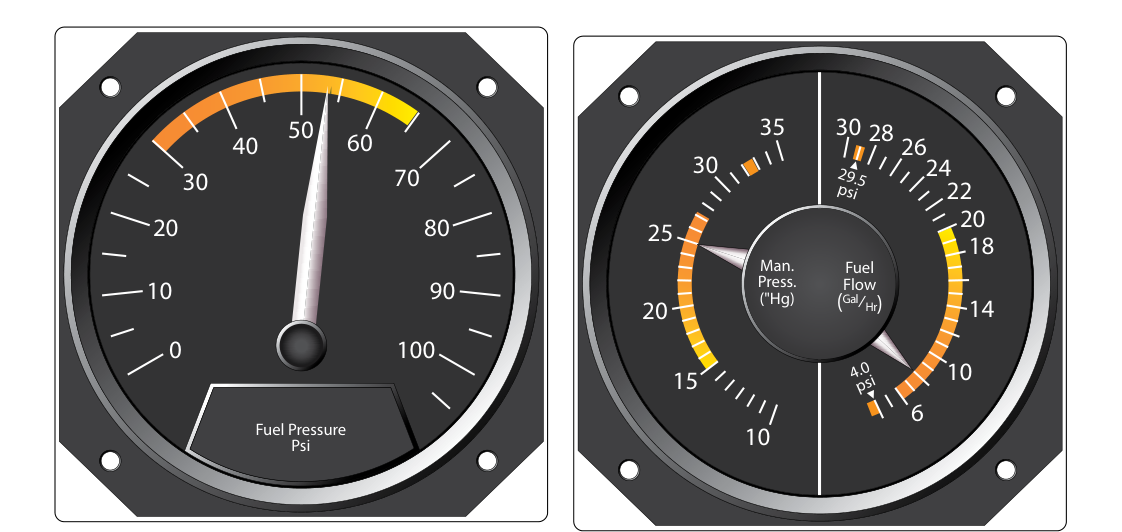
The manifold absolute pressure (MAP) gauge is one of the most important engine instruments on any aircraft equipped with a supercharged or turbocharged reciprocating engine, and it plays a meaningful role even on naturally aspirated powerplants. Unlike a simple vacuum gauge that measures pressure relative to the atmosphere, the MAP gauge measures absolute pressure — that is, the total air pressure in the intake manifold referenced to a perfect vacuum, expressed in inches of mercury (in. Hg). Because the density of the air-fuel charge entering the cylinders directly determines how much power the engine can produce, the MAP gauge gives the pilot and technician the clearest, most immediate look at engine power output available from a cockpit instrument.
For the AMT powerplant student, understanding how this instrument works, why it reads what it reads under various conditions, and how to systematically diagnose faults is essential knowledge for the FAA Powerplant Knowledge Test and for safe, competent maintenance practice. This article covers the operating principles, normal indications across flight phases, and a structured troubleshooting methodology grounded in FAA guidance.
How the MAP Gauge Works
The MAP gauge is, at its core, an absolute pressure measuring instrument. Its sensing element is typically an aneroid capsule — a sealed, corrugated metallic bellows or wafer that contains an internal reference vacuum (or near-vacuum). As manifold pressure changes, the external pressure acting on the capsule causes it to expand or contract. This mechanical movement is transmitted through a linkage to a pointer on a calibrated dial marked in inches of mercury. Because the reference inside the capsule is a fixed vacuum rather than the variable ambient atmosphere, the reading is always absolute, not gauge pressure. At sea level on a standard day, ambient pressure is 29.92 in. Hg, and a naturally aspirated engine idling will typically show 10–12 in. Hg due to the partial vacuum created by the pistons pulling against a partially closed throttle.
The gauge is connected to the intake manifold through a small-diameter sensing line, usually made of aluminum tubing or flexible hose. This line taps into the manifold downstream of the throttle valve and, on multi-engine aircraft or engines with multiple cylinders, typically reads from an averaging point or a single representative location. The smallness of the sensing line orifice acts as a damper, smoothing out rapid pressure pulsations caused by the opening and closing of intake valves, so the needle reads a stable average rather than bouncing wildly.
Naturally Aspirated vs. Supercharged/Turbocharged Engines
On a naturally aspirated engine, manifold pressure can never exceed ambient atmospheric pressure because the engine simply draws outside air through the induction system with no mechanical assist. At full throttle on the ground at sea level, MAP approaches (but does not quite reach) 29.92 in. Hg because of induction system losses such as filter restriction and duct friction. In cruise at altitude with a fixed-pitch propeller and open throttle, MAP decreases as the aircraft climbs because ambient pressure falls.
On a supercharged or turbocharged engine, the compressor stage can force air into the manifold at pressures above ambient, often reaching 36–45 in. Hg or more depending on the engine design. These engines require strict adherence to MAP limits specified in the engine's Type Certificate Data Sheet and the aircraft's Pilot's Operating Handbook / Aircraft Flight Manual (POH/AFM). Exceeding the MAP limit — commonly called over-boosting — can cause detonation, structural damage to pistons and connecting rods, and in severe cases catastrophic engine failure. The MAP gauge is therefore the primary protection tool against over-boost during ground runup and takeoff.
Normal Indications Across Flight Phases
Understanding normal MAP behavior helps the technician immediately recognize abnormal readings during runup, ground testing, and post-maintenance checks.
- Engine shutdown (engine not running): The gauge should read ambient atmospheric pressure — approximately 29.92 in. Hg at sea level on a standard day. A reading significantly lower than ambient with the engine off may indicate a ruptured aneroid capsule or a blocked/kinked sensing line holding residual vacuum.
- Idle on the ground: Typically 10–14 in. Hg for a naturally aspirated engine at normal idle RPM, reflecting the strong manifold vacuum generated when the throttle is nearly closed and the pistons are working hard to pull air past a small opening.
- Full-throttle takeoff (naturally aspirated): Should approach but not exceed ambient pressure, often reading 28–29 in. Hg, depending on induction system losses and density altitude.
- Full-throttle takeoff (turbocharged): Should reach the rated takeoff MAP limit, such as 39 in. Hg or similar — specific to the engine model — without exceeding it.
- Cruise at altitude: MAP is reduced and set per the approved power schedule in the POH/AFM, typically 20–25 in. Hg for a common light aircraft, combined with a specific RPM setting for a constant-speed propeller.
Why MAP Gauge Accuracy Matters
Aircraft technicians must appreciate that the MAP gauge is not merely a pilot convenience — it is a flight safety instrument. Inaccurate MAP indications can cause pilots to operate at engine power settings they cannot verify, leading to over-boost damage or, conversely, insufficient power on takeoff. On aircraft where fuel flow and mixture are optimized by reference to MAP, an erroneous reading can also drive poor mixture management, promoting either detonation (too lean at high power) or excessive fuel consumption and fouled spark plugs (too rich). The FAA's Aviation Maintenance Technician Handbook — Powerplant (FAA-H-8083-32) underscores that all engine instruments, including MAP gauges, must be maintained to manufacturer tolerances and calibrated periodically.
From a maintenance standpoint, the MAP gauge also provides valuable diagnostic data during magneto checks, compression tests, and fuel system inspections — any condition that changes the efficiency of the induction system will manifest as an abnormal MAP reading under controlled test conditions.
Troubleshooting MAP Gauge Discrepancies
A systematic approach prevents misdiagnosis and wasted labor. Follow the sensing system from the manifold tap back to the instrument face.
- Gauge reads ambient with engine running at idle: The most likely cause is a disconnected or ruptured sensing line. If the tube is open to atmosphere anywhere along its run, the capsule sees ambient pressure regardless of actual manifold conditions. Inspect the entire tubing run for cracks, loose B-nuts or clamps, and chafed sections where the tube contacts structure.
- Gauge reads lower than expected at full throttle: This can point to an induction system restriction — a clogged air filter, collapsed induction hose, or partially closed alternate air/carburetor heat valve left in the heat position. It can also indicate a leak downstream of the throttle plate (vacuum leak) that leans the mixture and reduces cylinder fill. Cross-reference with engine RPM behavior and EGT readings.
- Gauge reads higher than expected or over-boost condition on turbocharged engine: Possible causes include a stuck-open wastegate, a faulty upper deck pressure controller, or a failed absolute pressure controller. These are urgent findings; the engine must not be operated until the turbocharger control system is fully inspected and corrected per the applicable maintenance manual.
- Gauge needle is sluggish or does not respond to throttle changes: A partially blocked sensing line (moisture, corrosion, debris at the manifold fitting) will slow pressure equalization to the capsule. Remove and blow out the line, clean the manifold fitting, and retest. Dampening orifices that are over-restricted can produce the same symptom.
- Gauge reads incorrectly when compared to a calibrated test gauge: The aneroid capsule or the instrument mechanism itself may be faulty. Bench-test the instrument per the manufacturer's calibration procedure. Replace if the error exceeds allowable tolerances specified in the instrument's specification sheet. Instruments must be repaired or replaced — field recalibration of sealed aneroid instruments by unauthorized personnel is not permitted.
- Erratic or fluctuating needle: Normal slight fluctuation exists due to intake valve pulsing, but large swings suggest a loose sensing line fitting at the manifold end (intermittent connection), an internal capsule with a pinhole leak, or interference between the sensing line and a heat source causing vapor lock within the line.
Key Numbers and Rules
- MAP is always expressed in inches of mercury (in. Hg) for US-certificated aircraft.
- Standard sea-level ambient pressure is 29.92 in. Hg; a correctly functioning MAP gauge should show this value when the engine is not running at sea level on a standard day.
- On naturally aspirated engines, MAP cannot exceed ambient pressure — readings above ambient with the engine running indicate a faulty instrument or sensing line open to a pressurized source.
- On turbocharged/supercharged engines, the maximum MAP limit is engine-specific and found in the TCDS and POH/AFM — never exceed it even momentarily if possible.
- Sensing line inspections should be included in any annual inspection or 100-hour inspection as part of the general engine instrument systems check called for under 14 CFR Part 43, Appendix D, which addresses inspection scope in general terms rather than naming MAP sensing lines specifically.
- Any MAP instrument replaced or repaired must be verified for accuracy per the manufacturer's data before returning the aircraft to service under the general airworthiness standards of 14 CFR §91.7 and §43.13 (14 CFR §91.411 applies specifically to altimeter and static pressure system tests for IFR flight and does not cover MAP gauges).
Common Test Traps
- Confusing gauge pressure with absolute pressure: MAP is absolute — it includes atmospheric pressure in its reading. A gauge-pressure instrument zeroed at ambient would read zero at idle, not 10–14 in. Hg. The FAA test will probe whether you understand this distinction.
- Assuming a high MAP reading always means over-boost: On a naturally aspirated engine, a MAP reading equal to ambient is perfectly normal at full throttle on the ground. High MAP only becomes over-boost when it exceeds the engine's rated limit, which matters primarily on forced-induction engines.
- Overlooking the sensing line as a failure point: Many technicians jump to instrument replacement when the sensing line is the actual fault. Always inspect the pneumatic circuit first — it is far more common and easier to fix.
- Forgetting that MAP drops with altitude on naturally aspirated engines: If a student sees a question about why MAP decreases as an aircraft climbs (throttle wide open, naturally aspirated), the answer is decreasing ambient pressure — not a fault in the system.
- Misidentifying the normal engine-off indication: A MAP gauge that reads below ambient with the engine off and a good sensing line is showing a capsule failure (collapsed or cracked aneroid), not normal residual vacuum — the engine cannot sustain manifold vacuum once it stops turning.