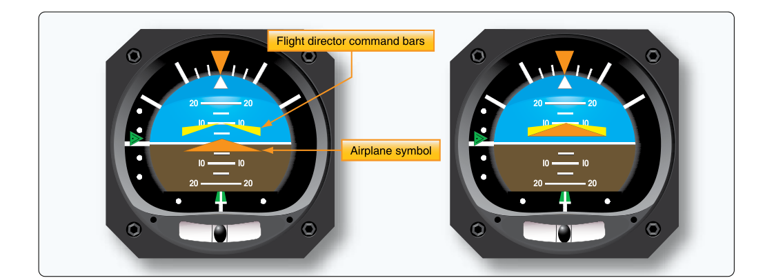
The flight director (FD) is one of the most powerful and most misunderstood tools in a modern glass cockpit. Rather than simply showing where the aircraft is, the flight director shows where the pilot needs to put the aircraft — specifically, what pitch attitude and bank angle to maintain in order to satisfy whatever mode the autopilot or flight management system (FMS) has been commanded. On a typical airline transport pilot (ATP) checkride and in daily line operations, the ability to read and precisely follow command bar cues is as fundamental as reading an altimeter. This article explains the mechanics of command bar interpretation, common display formats, underlying computation, and the discipline required to fly the bars accurately in every phase of flight.
Flight directors appear on the primary flight display (PFD) and, in older aircraft, on the attitude director indicator (ADI). They do not fly the aircraft — they command the pilot (or autopilot) to do so. When the autopilot is engaged, the autopilot servos follow the flight director commands automatically. When the autopilot is off, the pilot manually flies the aircraft to keep the command bars centered, a skill that demands smooth, coordinated control inputs and continuous scan.
Command Bar Formats: Single-Cue vs. Two-Cue
There are two broad display philosophies for presenting flight director guidance:
- Single-cue (V-bar or chevron): A single chevron-shaped symbol moves both vertically and laterally on the attitude display. The pilot flies the miniature aircraft symbol into the V-bar. If the V-bar is above the aircraft symbol, pitch up; if it is displaced laterally, bank in that direction. The single-cue format is ergonomically efficient because one symbol integrates both pitch and roll commands.
- Two-cue (cross-pointer or T-bar): Two independent bars are displayed — a horizontal bar commanding pitch and a vertical bar commanding roll. To satisfy the flight director, the pilot maneuvers the aircraft until the two bars form a centered cross at the aircraft reference symbol. This format is more common in modern transport-category aircraft and is what most pilots learn in Part 121 training. Each bar can be analyzed independently, which is helpful during unusual attitudes or system failures.
Regardless of format, the fundamental rule is the same: fly the aircraft symbol to the command bars, not the bars to the aircraft. The bars move to reflect a computed target; the pilot's job is to eliminate the error between the current attitude and the commanded attitude.
How the Flight Director Computes Its Commands
The flight director computer — whether a standalone flight guidance computer or a function embedded in the FMS — continuously calculates the pitch and bank angles needed to satisfy the active guidance modes. These modes are selected on the mode control panel (MCP) or flight control unit (FCU), and the active modes are annunciated on the PFD in the flight mode annunciator (FMA).
For example, if the autopilot/flight director is in heading select (HDG SEL) mode, the roll computer calculates the bank angle needed to turn to and maintain the selected heading. If the aircraft is on heading, the roll bar commands wings level. If the aircraft is 30 degrees right of the selected heading, the roll bar commands a standard-rate or maximum comfortable bank to the left. The pitch axis in this example might be in altitude hold (ALT HOLD), commanding whatever pitch attitude is needed to maintain the current altitude — which changes subtly as airspeed varies.
On an ILS approach with both localizer and glideslope captured, the roll bar commands lateral corrections to stay on the localizer centerline and the pitch bar commands vertical corrections to remain on the 3-degree glidepath. The computations are based on deviation signals from the VHF navigation receiver, filtered and scaled to produce smooth, flyable guidance. The closer the aircraft is to the centerline and glidepath, the smaller the bar deflections become.
Following the Bars: Technique and Discipline
Proper flight director following technique is characterized by small, anticipatory control inputs. The goal is to move the aircraft smoothly toward the commanded attitude and then relax the input as the bars re-center. Beginners frequently chase the bars — making aggressive inputs that overshoot the commanded attitude, causing the computer to demand a correction in the opposite direction, creating an oscillation. The cure is to recognize that the bars represent a target attitude, not a rate command. Move the aircraft attitude toward the bars at a moderate rate, and stop the input just before the bars center.
Pitch following is generally easier in calm air; turbulence causes the pitch bar to fluctuate as the flight director reacts to altitude and vertical speed deviations. Many airline standard operating procedures (SOPs) call for pilots to select an appropriate pitch mode (such as flight level change, vertical speed, or glidepath) and then monitor rather than micromanage. As a general practice in many airline environments, if the command bar demands an unusually large pitch or bank correction, pause and verify that the selected mode makes sense for the phase of flight, because extreme commands can indicate a mode error, a navigation source failure, or the system capturing an incorrect geometry. Specific pitch and bank thresholds for such cross-checks are aircraft- and operator-specific and are defined in the applicable AFM/FCOM and SOPs rather than by FAA handbook.
Mode Awareness: The Core ATP Skill
The Instrument Flying Handbook (FAA-H-8083-15) and the Instrument Procedures Handbook (FAA-H-8083-16) both emphasize that a pilot must always know what mode the flight director is in and what input that mode is using. Flying the bars without understanding the active mode is a form of automation complacency — one of the most frequently cited factors in transport-category accidents and incidents.
Before following any flight director command, verify on the FMA: What is the active roll mode? What is the active pitch mode? Is the armed mode about to capture? For instance, during a coupled ILS approach, you might see the roll mode arm as LOC and then become active as the localizer is captured, while the pitch mode transitions from ALT (or VNAV) armed to GS armed and then GS active as the glideslope is captured. Each transition changes what the command bars are responding to. A pilot who does not monitor the FMA may not notice when a mode fails to arm or transition, causing the aircraft to track the wrong guidance source.
Flight Director Use During Takeoff and Go-Around
Many transport-category aircraft display takeoff (TO) or go-around (GA) flight director modes on the ground or at the initiation of a missed approach. In TO mode, the pitch bar typically commands a target pitch attitude to achieve an initial climb profile consistent with obstacle clearance and noise abatement; the specific pitch target is aircraft-type and manufacturer specific and is defined in the applicable AFM/FCOM rather than by FAA handbook. The roll bar commands wings level until above a minimum maneuvering altitude.
In GA mode, activated by pressing the go-around button (usually on the thrust lever), the flight director immediately commands a positive pitch attitude and wings level regardless of the approach track. The pilot follows the pitch bar to establish a climb, confirms TOGA thrust, retracts flaps on schedule, and then selects the appropriate climb and navigation modes. Missing this prompt can lead to a delayed climb — a critical safety concern during a low-altitude missed approach.
Key Numbers and Rules
- ILS glideslope angle: Typically 3 degrees. The pitch bar on a captured glideslope commands adjustments around this geometry.
- Standard-rate turn: 3 degrees per second; flight director roll bar bank angle limits are aircraft-type and manufacturer dependent and are defined in the applicable AFM/FCOM rather than by a single FAA-published figure.
- FMA scan: Check the FMA at every mode transition — arm to capture, approach transitions, altitude constraints.
- Command bar validity: Many aircraft blank or flag the flight director bars when a navigation source fails or becomes unreliable. A flagged bar means do not follow — revert to raw data.
- Autopilot off, FD on: The pilot manually flies to the bars; precision requires the same scan and technique as autopilot-coupled flight.
Common Test Traps
- Confusing the flight director with the autopilot: The flight director only provides guidance cues. It does not move control surfaces. With the autopilot off, the airplane does exactly what the pilot inputs — the bars just show where the pilot should aim.
- Ignoring the FMA: ATP knowledge test and practical test questions often test whether candidates understand that following the bars without verifying the active mode is insufficient. The mode determines what the bars are responding to.
- Chasing the bars: Aggressive corrections that overshoot the commanded attitude are a classic hand-flying error. The bars represent a target attitude, not a rate-of-movement command.
- Flying a flagged flight director: If the flight director bars are removed or flagged due to a system fault, continuing to look for bar guidance rather than transitioning to raw data instrument flying is a significant error.
- Assuming TO/GA pitch attitude is fixed: The commanded pitch in TO or GA mode varies by aircraft type, weight, configuration, and SOP. Do not assume a generic value; always know your aircraft-specific procedures.
Mastering flight director command bar interpretation is ultimately about disciplined scan, deep mode awareness, and smooth aircraft control. The bars are a tool to help achieve precision — but they only serve that purpose when the pilot understands, monitors, and intelligently follows them through every phase of flight.