The Flight Management System (FMS) is one of the most consequential pieces of avionics ever installed in a transport-category aircraft. Far more than a sophisticated GPS receiver, the FMS serves as the computational backbone of modern airline operations — continuously calculating the most efficient route, altitude, and speed profile while providing guidance commands to the autopilot, autothrottle, and primary flight displays. For an Airline Transport Pilot (ATP) candidate, understanding how the FMS is built, how its subsystems communicate, and where the system's inherent limitations lie is not optional knowledge. It is foundational to managing automation safely and to passing both the ATP knowledge test and the practical examination.
This article traces the FMS from its core computing hardware through its major functional components, explains how each element contributes to the overall guidance picture, and highlights the operational and regulatory considerations every ATP must internalize.
Core Architecture: The Flight Management Computer
At the heart of every FMS is one or more Flight Management Computers (FMCs) — sometimes called Flight Management Computer Systems (FMCSs) or, on some Airbus platforms, Flight Management and Guidance Computers (FMGCs). Most transport-category aircraft carry two or three FMCs operating simultaneously, typically in an active/cross-monitoring or triple-redundant configuration. Redundancy is not a luxury; it is a certification requirement driven by the criticality of the navigation and performance functions these computers perform.
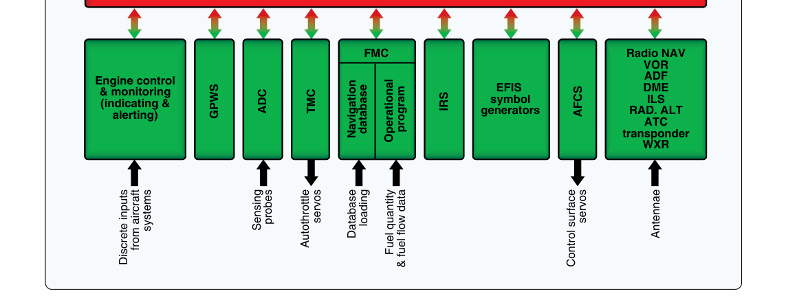
Each FMC is essentially a dedicated processor running proprietary software that manages three broad domains: navigation management, performance management, and flight-path prediction. The computer receives data from multiple sensor systems, performs continuous calculations, and outputs guidance data to the autopilot flight director system (AFDS) and autothrottle. On many aircraft, when two FMCs are installed they continuously cross-check their outputs, and disagreement alerting is a common design feature; the specifics of this behavior are aircraft-specific and defined in the applicable FCOM/AFM rather than by a universal FAA rule, so crews must know their particular aircraft's disagreement-alerting logic and follow the associated procedures before relying on automated guidance.
The Navigation Database
The FMC cannot navigate without reference data, and that data lives in the Navigation Database (NDB) — a structured electronic library stored in non-volatile memory (historically on data-loader cartridges, now often via electronic data-loading units or Ethernet connections). The navigation database contains waypoints, airways, airports, runways, instrument procedures (SIDs, STARs, approaches), navaids (VORs, NDBs, ILS frequencies), and airspace boundaries, all encoded according to ARINC 424 data-formatting standards.
Critically, the navigation database is cycle-limited. The FAA and ICAO publish aeronautical information on a 28-day aeronautical information regulation and control (AIRAC) cycle, and operators load updated databases in step with this cycle to keep navigation data current. There is no single blanket FAA rule mandating that every operator reload a database every 28 days regardless of circumstance; rather, the database must be current and valid for the specific procedures being flown, with currency requirements governed by the operator's airworthiness and operational approvals and operations specifications. Flying with an expired database is not automatically illegal for every operation, but using FMS-derived lateral navigation (LNAV) or vertical navigation (VNAV) on an instrument procedure requires a current, verified database under the applicable instrument flight rules and airline operations specifications. ATP candidates must understand that a crew who loads an old database and executes an RNAV approach based on it is accepting both a safety risk and a regulatory exposure.
Performance Database and the Cost Index
Alongside navigation data, the FMC houses a Performance Database that models the specific aircraft's aerodynamic and engine performance characteristics — lift curves, drag polars, thrust limits as a function of altitude and temperature, fuel-flow schedules, and more. This data is aircraft-specific and must match the aircraft's actual configuration (engine type, weight variant, winglet installation, etc.).
The FMC uses the performance database to compute optimum cruise altitudes, step-climb profiles, maximum-range cruise (MRC) speeds, and long-range cruise (LRC) speeds. The Cost Index (CI) is the primary variable the crew or dispatcher uses to bias this optimization. Cost Index is generally expressed as the cost of time (per minute) divided by the cost of fuel (per unit weight); the exact units vary by manufacturer — for example, Airbus commonly expresses CI in kg/min while Boeing uses other weight/time conventions — so describing CI simply as a fuel-mass-per-unit-time figure oversimplifies it. A Cost Index of zero directs the FMC to fly at maximum range speed, minimizing fuel burn with no regard for time. A very high Cost Index tells the FMC that crew costs and schedule recovery matter more than fuel, pushing speeds toward the maximum operating limit (MMO/VMO). Most airlines publish a standard CI for each route that balances their actual operating economics.
Sensor Integration: How the FMC Knows Where It Is
The FMC does not generate position data in isolation. It acts as a sensor fusion engine, accepting position and state data from multiple independent sources and blending them into a single best-computed position (BCP). Typical sensor inputs include:
- Inertial Reference Systems (IRS/INS): Ring-laser-gyro or fiber-optic-gyro platforms that provide attitude, heading, groundspeed, and position through double-integration of accelerometer data. Manufacturer specifications typically describe modern IRS drift rates on the order of 1–2 nautical miles per hour or less, though this figure comes from equipment specifications rather than an FAA-published standard, and the system must be initialized on the ground.
- GPS receivers: GNSS data provides high-accuracy absolute position continuously updated. On modern aircraft, multi-mode receivers (MMRs) combine GPS with ILS/VOR functions in a single LRU.
- VOR/DME and DME/DME: The FMC can compute position by tuning ground-based navaids automatically, using DME ranging from two or more stations for a geometric fix. This capability is important in areas of GPS signal degradation.
- ILS localizer and glideslope: Used for final approach guidance and cross-checking.
The FMC continuously weights these inputs, preferring GPS when available and healthy, falling back to radio navigation and IRS blending when GPS is unavailable or flagged. The resulting BCP is what drives the magenta (or cyan, depending on manufacturer) flight-path deviation indicators on the PFD and ND.
The Control Display Unit (CDU)
The crew interacts with the FMC through the Control Display Unit (CDU) — the keyboard-and-screen interface (sometimes called the MCDU, or Multifunction CDU, on Airbus). The CDU is how pilots enter the route, select procedures from the navigation database, initialize the IRS, set performance variables (weights, Cost Index, cruise altitude, flex/assumed temperature for takeoff), and review FMC predictions. On Boeing platforms the CDU uses line-select keys (LSKs) alongside a scratchpad for data entry. Airbus uses a similar concept with MCDU pages. Both designs require methodical, checklist-driven data entry; an incorrectly entered route or performance figure can propagate silently through every downstream calculation the FMC makes.
Integration with Autopilot, Autothrottle, and Displays
The FMC outputs guidance to the Autopilot Flight Director System (AFDS) via a digital data bus (typically ARINC 429 or ARINC 629 on older Boeing widebodies, with newer high-speed data network architectures used on more recent widebody generations). In LNAV mode the autopilot follows the FMC's computed lateral track. In VNAV mode the autopilot and autothrottle together follow the FMC's computed vertical profile, respecting altitude constraints embedded in SIDs, STARs, and approach procedures from the navigation database. The FMC also drives the Navigation Display (ND), painting the route, waypoints, weather radar overlay, traffic (if integrated), and terrain depictions that give crews their situational awareness picture.
It is crucial to understand the mode control panel (MCP/FCU) relationship: the MCP sits between the crew and the FMC. When the crew selects LNAV or VNAV on the MCP they are commanding the autopilot to follow FMC guidance. If LNAV is disengaged, the autopilot reverts to heading mode; if VNAV is disengaged, it reverts to altitude-hold or V/S mode. Crews must always know which automation modes are active and which layer of the system hierarchy is generating the guidance.
Why FMS Architecture Matters for Safety
A significant proportion of controlled-flight-into-terrain (CFIT), unstabilized approach, and level bust incidents have been linked to FMS mismanagement — crews who trusted FMC outputs without verifying the underlying data, who misunderstood active modes, or who failed to cross-check FMC position against raw navaid data. The FAA's risk management framework emphasizes that automation does not eliminate the need for manual cross-checking; it changes the nature of the monitoring task. An ATP must be equally proficient at reading FMC pages critically and at flying the aircraft manually when automation is unreliable or inappropriate.
Key Numbers and Rules
- 28-day AIRAC cycle: Aeronautical information, including navigation database content, is published on this 28-day cycle; procedures in the database must be current and valid for use on instrument approaches under IFR, per operator-specific approvals and ops specs.
- IRS alignment time: Typically 5–10 minutes on the ground; alignment in flight is less accurate and generally not permitted operationally.
- IRS drift: Manufacturer specifications for modern ring-laser-gyro units commonly describe drift on the order of 1–2 NM per hour; FMC blending with GPS effectively bounds accumulated position error during flight.
- Cost Index range: Typically 0 (minimum fuel speed) to 999 or 9999 (maximum speed) depending on manufacturer convention; airline-published CI values vary widely by route and aircraft type.
- ARINC 424: The industry standard data format for encoding navigation procedures in FMC databases; understanding this standard underpins understanding why certain complex procedures may not encode perfectly and require crew verification.
- Redundancy: Most transport-category FMS installations use dual or triple FMC architecture with cross-monitoring; a single FMC failure is typically an alert condition, not a loss of navigation capability.
Common Test Traps
- Confusing the CDU with the FMC: The CDU is only the interface device; the FMC is the computer that does the actual computation. They are separate line-replaceable units (LRUs).
- Assuming GPS alone drives the FMC: The FMC uses sensor blending. GPS failure does not mean total navigation failure; the system reverts to IRS and radio navigation blending, though accuracy degrades over time.
- Ignoring Cost Index implications on speed: Test questions may ask what happens to cruise speed when CI is increased — the answer is it increases (toward MMO), burning more fuel but saving time.
- Thinking an expired navigation database automatically grounds the aircraft: The regulatory picture is nuanced — the aircraft can be flown, but FMS-based RNAV instrument procedures may not be legally or safely executed with an expired database. Know the distinction.
- Misidentifying the mode hierarchy: The FMC generates guidance; the AFDS executes it; the MCP mediates between them. Selecting a mode on the MCP that conflicts with an active FMC mode can produce unexpected behavior — a favorite trap in scenario-based ATP test questions.