Airframe structures endure constant vibration, thermal cycling, and exposure to moisture. Under these conditions, two closely related but mechanically distinct corrosion processes — fretting corrosion and galvanic (dissimilar metal) corrosion — can silently degrade structural joints long before visible damage appears on the surface. Aviation maintenance technicians (AMTs) must understand the mechanics of both processes, recognize their characteristic signatures, and apply the correct preventive treatments during assembly and overhaul. Errors in this area can compromise load-carrying members and fastener holes in ways that are difficult to detect and potentially catastrophic.
This article addresses both hazards in depth: how each develops, why the airframe environment makes them especially dangerous, the specific materials and locations most at risk, and the precise preventive measures described in FAA maintenance guidance. Together, these two topics form a critical pillar of metallic airframe corrosion control for the AMT Airframe certification.
Fretting Corrosion: Mechanics and Development
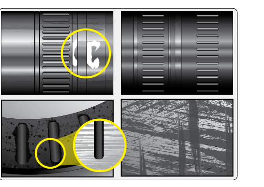
Fretting corrosion — sometimes called wear oxidation or false brinelling — occurs when two surfaces in contact undergo extremely small, repetitive relative motion (micro-slip) while simultaneously being subjected to a load that holds them together. This combination is unique: the surfaces cannot slide freely, yet they cannot remain perfectly still either. The result is a destructive three-stage cycle.
In the first stage, the oscillatory micro-motion abrades the thin oxide film that naturally protects most metals. On aluminum alloys, for example, this film is aluminum oxide (Al₂O₃), a hard, passive layer only a few nanometers thick. Once the oxide is disrupted, fresh metal is exposed. In the second stage, that fresh metal oxidizes almost immediately in the presence of atmospheric oxygen or moisture, producing a new oxide layer. In the third stage, the continuing micro-motion abrades the new oxide, generating fine oxide debris that accumulates in the joint. This debris — sometimes described as a reddish-brown powder on steel (iron oxide) or a grayish-black powder on aluminum — is harder than the parent metal and acts as an abrasive, accelerating surface pitting and material removal with each subsequent cycle.
The damage left behind includes surface pits, shallow craters, and a frosted or etched appearance in the contact zone. More critically, fretting damage creates stress concentration sites. Because airframe joints are also subjected to cyclic fatigue loading, the pits and surface irregularities produced by fretting become nucleation points for fatigue cracks. This synergy between fretting and fatigue — called fretting fatigue — can reduce the fatigue life of a component far below what either mechanism would produce independently. Fastener holes in wing skins, lap joints in fuselage frames, and spline couplings in control systems are among the highest-risk locations.
Where Fretting Occurs on the Airframe
Any joint that is tight enough to resist macro-slip but exposed to vibration is a candidate for fretting. On a typical light aircraft or transport-category airframe, the most common locations include:
- Fastened lap joints: Fuselage skin panels joined with rivets or bolts experience micro-relative motion as the structure flexes in flight and on rough runways.
- Fastener holes: The shank of a rivet or bolt bears against the hole wall; repeated loading causes micro-slip at the shank-to-hole interface, producing fretting pits that can propagate into fatigue cracks.
- Splines and keyed shafts: Control system splines transmit torque while simultaneously experiencing vibratory loads, creating ideal fretting conditions.
- Bearing surfaces and seat tracks: Even relatively rigid press-fit bearings can experience micro-motion under vibration.
- Engine mount attach fittings: These joints combine high vibration amplitude from the powerplant with significant clamping loads.
Galvanic (Dissimilar Metal) Corrosion: Mechanics and Development
Galvanic corrosion is an electrochemical process that occurs when two metals with different electrochemical potentials (different positions in the galvanic series) are placed in electrical contact in the presence of an electrolyte. The electrolyte is any electrically conductive liquid — moisture, rainwater, condensation, aviation fluids, or even humid air trapped in a joint. In this electrochemical cell, the less noble metal acts as the anode and corrodes preferentially, while the more noble metal acts as the cathode and is protected.
The driving force is the potential difference between the two metals. The farther apart two materials are in the galvanic series, the more aggressive the galvanic attack on the anodic member. Common airframe metal pairings that produce significant galvanic couples include aluminum alloy in contact with steel fasteners, copper alloy fittings against aluminum structure, and magnesium alloy components adjacent to almost any other structural metal. Magnesium is near the active (anodic) end of the galvanic series and will sacrifice itself rapidly when coupled with more noble metals.
The area ratio between anode and cathode dramatically affects the corrosion rate. A small anode coupled to a large cathode produces an extremely aggressive corrosion cell: the anodic current density is concentrated on a small surface, causing rapid, localized attack. This is why using steel fasteners in aluminum structure can be tolerable when the fasteners are coated and sealed (minimizing electrical contact), but a bare steel rivet in direct contact with a large aluminum panel creates a highly unfavorable area ratio with potentially rapid aluminum corrosion around the fastener hole.
Why These Hazards Are Especially Dangerous in Aviation
Both fretting and galvanic corrosion are insidious because they are predominantly hidden. Fretting damage develops inside joints and beneath fastener heads where visual inspection cannot reach without disassembly. Galvanic corrosion often begins at faying surfaces and works outward, so the first visible sign — paint bubbling, white powder (aluminum oxide) around fasteners, or rust streaking — represents damage that has already progressed significantly beneath the surface. By the time the inspector can see the problem, structural cross-section loss and fatigue crack nucleation may already have occurred in load-critical areas.
The airframe environment makes these processes worse. Pressurization and depressurization cycles pump moist air into and out of lap joints. Temperature swings cause differential thermal expansion between dissimilar materials, generating micro-motion that drives fretting. Condensation collects in bilge areas, providing a persistent electrolyte for galvanic cells. These factors mean that corrosion prevention must be engineered into every assembly, not treated as an afterthought.
Prevention: Fretting Corrosion
The primary strategies for preventing fretting are reducing relative motion, reducing surface stress, and introducing a barrier between contacting surfaces. FAA guidance and accepted maintenance practice include the following measures:
- Proper torque and fit: Achieving correct clamp-up force in fastened joints reduces micro-slip by increasing friction between faying surfaces. Under-torqued fasteners allow more relative motion; over-torqued fasteners can cause their own structural damage.
- Corrosion-inhibiting compounds (CICs) at faying surfaces: Sealants, wet-installed fasteners, and zinc chromate or equivalent primer applied to faying surfaces fill micro-gaps, exclude moisture, and reduce the coefficient of friction, all of which limit fretting damage.
- Interference-fit fasteners: In critical fastener holes, interference-fit installation expands the fastener shank to put the hole wall in compression, which both reduces micro-slip and improves fatigue resistance by countering applied tensile stresses.
- Surface treatments: Shot peening induces compressive residual stresses in the surface layer, increasing resistance to fretting fatigue crack initiation.
Prevention: Dissimilar Metal Contact
The fundamental strategy is to break the electrochemical circuit by preventing direct metal-to-metal contact and excluding electrolytes. Specific measures include:
- Insulating barriers: Zinc chromate primer, sealants, insulating tapes, and anodized or chemically converted coatings (such as Alodine/chromate conversion on aluminum) interrupt the galvanic circuit between dissimilar metals.
- Cadmium-plated or coated fasteners: Cadmium is close in the galvanic series to aluminum, making cadmium-plated steel fasteners far more compatible with aluminum structure than bare steel fasteners.
- Select compatible metals when possible: Structural design should minimize the potential difference between adjacent materials. Where dissimilar metals must be used, select pairs that are close together in the galvanic series.
- Sealant application at all faying surfaces: Wet-sealing prevents electrolyte intrusion, which is a prerequisite for any galvanic cell to function. No electrolyte means no galvanic corrosion.
- Paint and coating systems: A complete, unbroken primer and topcoat system over the entire structure acts as the first line of defense against moisture reaching any metal-to-metal interface.
Key Numbers and Rules
- Fretting damage is characterized by oxide debris: reddish-brown powder (iron oxide) on steel, grayish-black powder on aluminum alloys.
- A small anode / large cathode area ratio is the most aggressive galvanic configuration and the most dangerous in airframe joints.
- Magnesium alloys are among the most anodic (least noble) common airframe metals and must be isolated from all other structural metals with coatings and sealants.
- Cadmium plating on steel fasteners is specifically chosen for aluminum structure because cadmium's galvanic potential is close to aluminum, minimizing the driving voltage of any galvanic cell.
- Interference-fit fasteners simultaneously address fretting (by reducing micro-slip) and fatigue (by introducing beneficial compressive stress in the hole).
Common Test Traps
- Confusing fretting with ordinary wear: Fretting requires a combination of contact load and micro-oscillatory motion — it is not simple sliding wear. The key identifier is the fine oxide debris and pitting left at the contact interface.
- Assuming visible corrosion means recent onset: Both fretting and galvanic corrosion are hidden processes. Visible evidence typically represents advanced damage; the structurally significant damage is usually subsurface and preceded the visible signs.
- Overlooking the area ratio rule: Many students recall that dissimilar metals corrode, but forget that the relative surface areas of anode and cathode determine the severity. A small anodic area relative to the cathode produces the most rapid attack — exactly the situation with a bare steel fastener in a large aluminum panel.
- Treating priming or painting as sufficient without sealing faying surfaces: External coatings alone do not protect faying surfaces. Sealant must be applied to the mating surfaces before assembly to exclude the electrolyte from the joint interior.
- Forgetting that fretting damage is a fatigue multiplier: Test questions may describe a component with surface pitting at a joint and ask for the significance. The correct answer acknowledges not just surface damage but the greatly increased risk of fatigue crack nucleation at those pits.